Catheter Assembly With User-Assisting Handle

Inactive Publication Date: 2013-04-25
NOVOSTENT CORP
View PDF3 Cites 16 Cited by
  • Summary
  • Abstract
  • Description
  • Claims
  • Application Information

AI Technical Summary

Benefits of technology

The patent text describes some new deployment systems that have handles that are easy to use with one or two hands, regardless of the implant's configuration. These systems require a low and consistent force to work, which is an important advantage. To use them, an operator rotates a knob or similar feature to release a driving force that is attached to the outer sheath. This allows for controlled retraction of the sheath and release of the implant.

Problems solved by technology

Due to this configuration, several potentially undesirable effects are present during deployment of the prosthesis.
The frictional force may be prohibitive to easy sheath withdrawal, and the effort to deliver adequate force may shift the position of the prosthesis.
However, this high outward acting force can result in a high frictional force during deployment, particularly at initiation of deployment.
Overcoming a high deployment force can be undesirable from safety, ergonomic, and control perspectives, e.g. placement accuracy.
Additionally, prostheses are typically available in multiple configurations, e.g. length and diameter, causing variations in deployment forces required.

Method used


Image

  • Catheter Assembly With User-Assisting Handle
  • Catheter Assembly With User-Assisting Handle
  • Catheter Assembly With User-Assisting Handle

Examples


Embodiment Construction

[0030]The following description will typically be with reference to specific structural embodiments and methods. It is to be understood that there is no intention to limit the invention to the specifically disclosed embodiments and methods but that the invention may be practiced using other features, elements, methods and embodiments. Preferred embodiments are described to illustrate the present invention, not to limit its scope, which is defined by the claims. Those of ordinary skill in the art will recognize a variety of equivalent variations on the description that follows. Like elements in various embodiments are commonly referred to with like reference numerals.

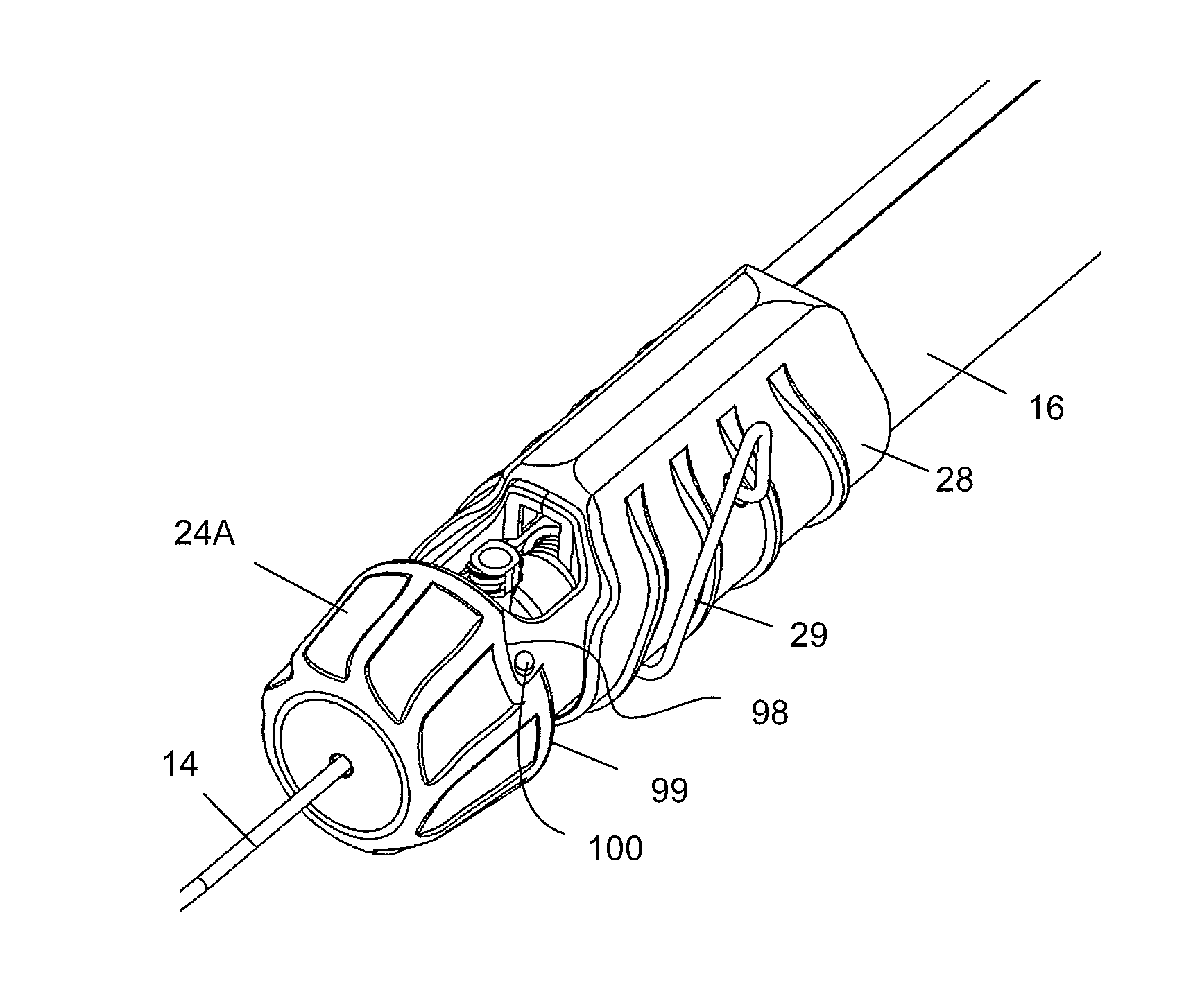
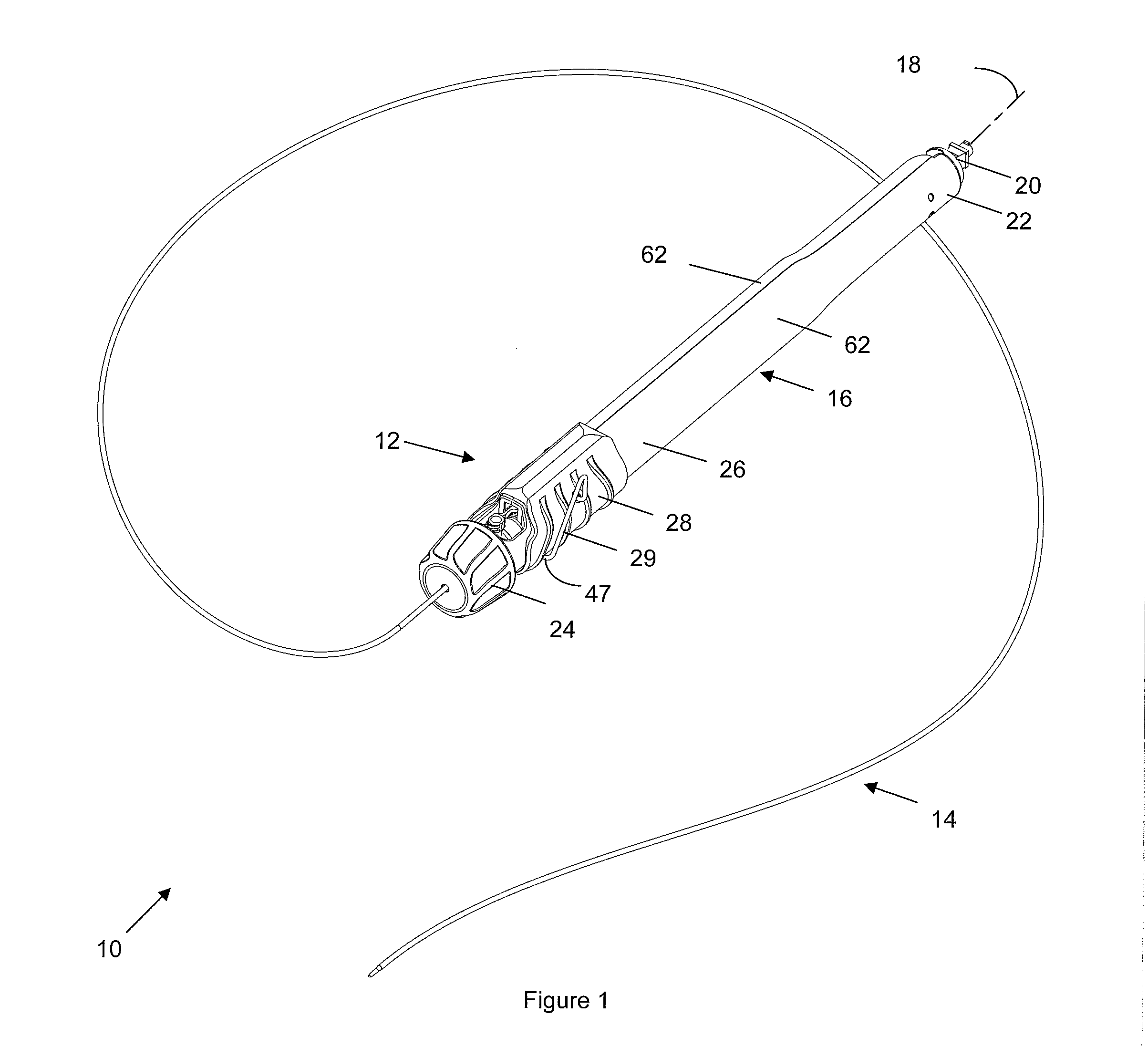
[0031]FIG. 1 illustrates one example of a catheter assembly 10 including a handle 12 and a catheter 14. Handle 12 includes a housing 16 defining a housing axis 18 with a flush port 20 at a proximal end 22. Handle 12 has a deployment knob 24 rotatably mounted to the distal end 26 of housing 16. Housing 16 also has a handl...


PUM


Abstract

A catheter assembly includes a catheter, including an inner member and a sheath, extending from a handle. The handle includes a housing, a braking assembly, a carriage and a carriage driver. The braking assembly comprises a braking element within the housing interior and a braking element rotator. The carriage comprises at least one carriage braking surface engaging the braking element. The carriage driver, such as a spring, biases the carriage towards the proximal end of the handle. The inner member has a proximal end secured to the housing. The sheath has a proximal end secured to the carriage. Rotating the braking element causes the carriage to move proximally as the carriage braking surface slides along the braking element. This causes the sheath to move proximally relative to the inner member.

Description

BACKGROUND OF THE INVENTION[0001]The present invention relates to a handle for implant deployment and to an associated deployment assembly. Delivery devices have long been used for a variety of medical procedures including maintaining passages, cavities or lumens in vessels, organs or ducts, occlusion of such vessels, delivering medical treatments, and other interventions. Today, there is a wide range of intravascular prostheses on the market for use in the treatment of aneurysms, stenosis, and other vascular disorders. Stents, stent grafts, and other vascular prostheses are well known for treating a myriad of diseases and illnesses in vasculature. For percutaneous interventions, many vascular prostheses are inserted into the body within a catheter and deployed at the desired treatment site. The present invention relates to a device for controlled deployment of a vascular prosthesis, such as a stent, stent-graft, filter or occlusion device, for treatment of vascular disorders.[0002]...

Claims


Application Information

Patent Timeline
IPC IPC(8): A61F2/84
CPCA61F2/966A61F2002/9517A61F2250/0018A61F2230/0091A61F2230/0019A61F2/9517
Inventor LUBINSKI, ALEXANDER ARTHURLEOPOLD, ERIC W.MARTIN, GERALD RAY
Owner NOVOSTENT CORP
Why Eureka
Try Eureka