

Fluid actuated energy generator
a technology of energy generators and fluids, applied in sea energy generation, tide stream/damless hydropower, electrical equipment, etc., can solve the problems of large range of input fluid velocity, high cost of existing units, and inability of devices to work across potentially large input fluid velocity ranges
Inactive Publication Date: 2013-05-09
CORCOST LTD
View PDF13 Cites 4 Cited by
- Summary
- Abstract
- Description
- Claims
- Application Information
AI Technical Summary
Benefits of technology
The invention is a device with a simple adjustable mechanism that can change its shape both inside and outside. This allows it to adapt to different flow patterns and make adjustments to its characteristics. The device is not limited to a single type of device and can be used in various situations. This flexibility ensures the device is always operating at its best, even in turbulent or unstable fluid conditions.
Problems solved by technology
However the majority of these devices suffer from the same common problems.
The first common problem they suffer is cost, typically existing units are very expensive not only to manufacture but also to install and uninstall.
The second common problem is one of the ability of devices to work across a potentially large range of input fluid velocity which is typical incurred in most applications.
The third common problem is scalability where the majority of devices are not able to be cost effectively utilised at a medium or small scale.
A fourth common issue is fluctuations in the source energy which can lead to local area flicker caused by starts and changing conditions of the source.
In particular to sub surface types of devices further common issues are apparent such as the changing environmental conditions and the usage of hydraulics.
Currently sub surface devices are fixed and as such cannot change to accommodate fluctuating water depths.
The devices require a depth of water in which to operate and this prohibits many suitable locations being used for renewable energy generations.
The sixth issue is the use of hydraulics and this has many considerations.
The second such consideration is the limited nature in terms of the viscosity of the oil such that the overall speed at which a device can operate is low and typically not changeable.
The third consideration is the large weight and size of any hydraulics assembly which adds complexity to all aspects of the product including its manufacture, shipment to location and maintenance.
Finally but not limited to is the environmental issues surrounding oil whereby the prior art hydraulic systems require a significant amount of oil and thus there are environmental concerns whereby if a leak occurred, not only would the device reduce its output capacity and eventually stop working, their would also be considerable environmental contamination.
Method used
View moreImage
Smart ImageViewing Examples

Examples
first embodiment
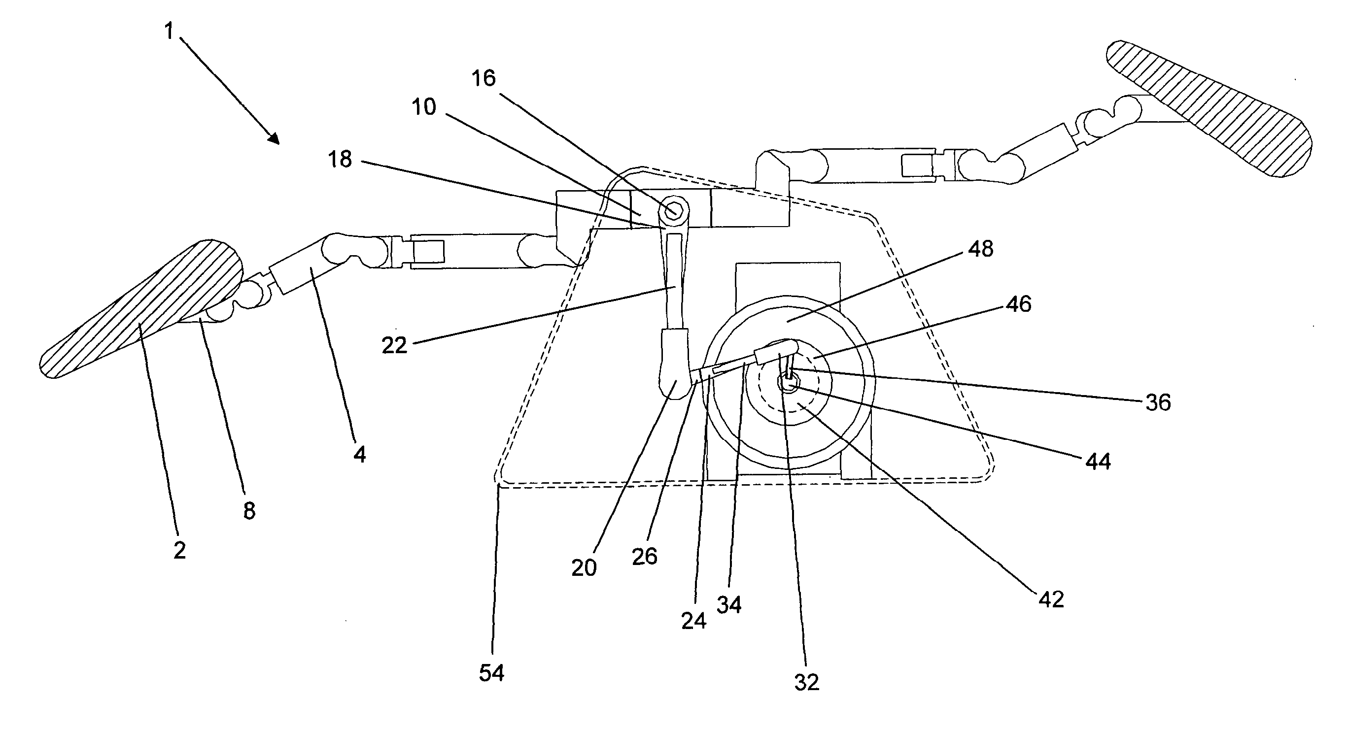
[0034]FIG. 1; a side view of the invention
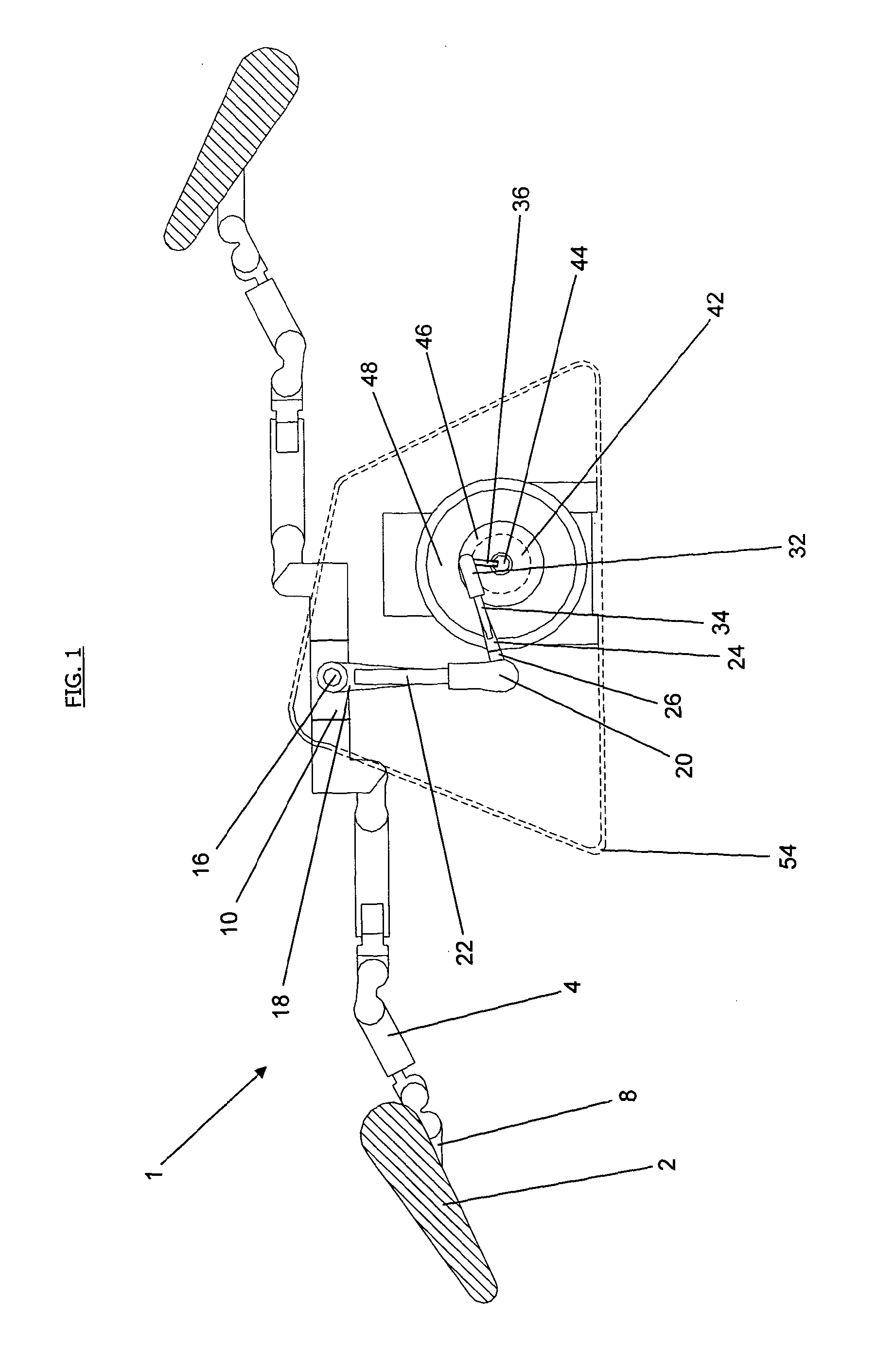
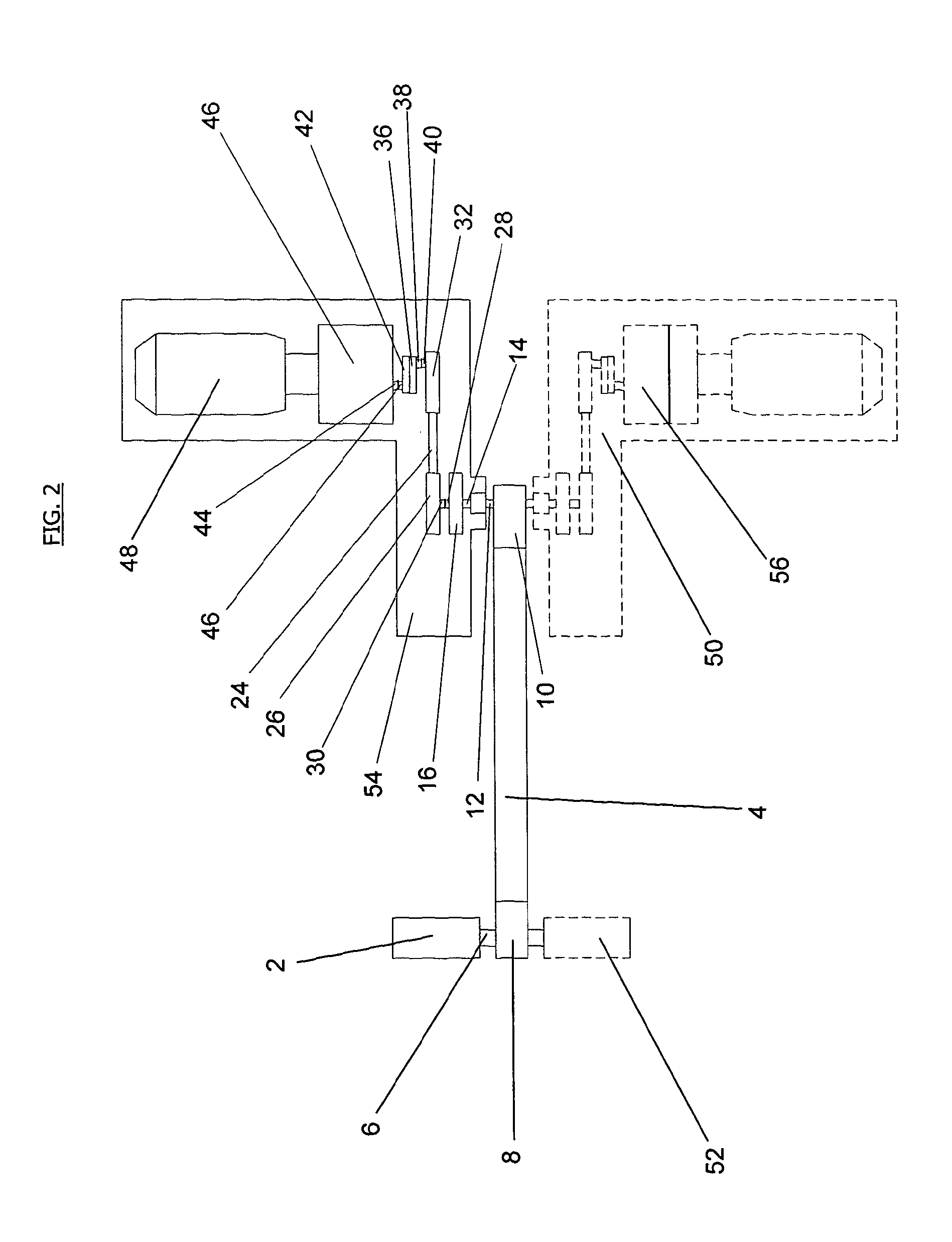
[0035]FIG. 2; a plan view showing a second embodiment of the invention which is substantially the same as the first embodiment but illustrates how a second generator and blade might be incorporated into the embodiment of FIG. 1.
[0036]FIG. 3; a side view of a gearbox able to be used in any embodiment
[0037]FIG. 4; a side and section view of a linear actuator able to be used in any embodiment
[0038]FIG. 5; a plan view of an actuating arm which is able to be used in any embodiment
third embodiment
[0039]FIG. 6; a side view of the invention
fourth embodiment
[0040]FIG. 7; a plan view of the invention
Login to View More PUM
 Abstract
A fluid actuated energy generator comprises; an output shaft (44) rotatably mounted in a housing (54), a first linkage (36) arranged to rotate with the output shaft (44) and extending in an axis orthogonal to the axis of the output shaft (44), a second linkage (22) rotatably mounted in relation to the first linkage at the radially most distal end thereof, the first and second linkages (36, 22) arranged for rotation in parallel planes, an actuating arm (4) rotatably mounted in relation to the second linkage (22) at the radially most distal end thereof and arranged for rotation in a parallel plane with the first and second linkages (36,22) and at least one blade (2) rotatably mounted in relation to the arm (4) at the radially most distal end thereof and arranged for rotation in a parallel plane with the arm (4), first and second linkages (36, 22), the longitudinal axis of the blade (2) extending orthogonally to the longitudinal axis of the arm (4).
Description
[0001]The present invention relates to renewable energy apparatus and in particular to devices which convert energy from natural sources such as wind, wave and tidal changes into a form which can be used to generate electrical power for domestic and industrial use.BACKGROUND TO THE INVENTION[0002]Many devices have been invented for the production of electricity from natural means such as wind, wave and tidal. However the majority of these devices suffer from the same common problems. The first common problem they suffer is cost, typically existing units are very expensive not only to manufacture but also to install and uninstall. The second common problem is one of the ability of devices to work across a potentially large range of input fluid velocity which is typical incurred in most applications. The third common problem is scalability where the majority of devices are not able to be cost effectively utilised at a medium or small scale. A fourth common issue is fluctuations in the...
Claims
Login to View More Application Information
Patent Timeline
 Patent Type & Authority Applications(United States)
IPC IPC(8): F03B13/00
CPCF03B13/1805F03B13/188F03B13/264F03B15/00F03B13/00F03B17/062F05B2240/97Y02E10/28Y02E10/38F03B17/06Y02E10/30Y02E10/20
Inventor CORCORAN, STEVEN
Owner CORCOST LTD