
Fuel injector

a fuel injector and variable geometry technology, applied in the direction of machines/engines, combustion types, lighting and heating apparatus, etc., can solve the problems of changing the total combustor area for fluid input, increasing co emissions, and increasing the nox emission of combustor, so as to achieve greater engine operating range and low nox emission

Inactive Publication Date: 2007-04-10
ROLLS ROYCE PLC
View PDF13 Cites 20 Cited by
  • Summary
  • Abstract
  • Description
  • Claims
  • Application Information

AI Technical Summary

Benefits of technology

[0014]Embodiments of the invention ensure that velocity of fluid flow downstream of the fuel inlet remains high and thus renders the fuel injector less susceptible to flashback. It may be operated in more highly throttled conditions. It may maintain optimum fuel / air mix for low NOx emissions over a greater engine operating range.

Problems solved by technology

If the percentage of fuel decreases below the optimum then CO emissions increase and the combustor may go out because the flame temperature has fallen too low.
A problem with this type of system is that a change in the fuel injector geometry may result in a change in the total combustor area for fluid input with a consequent change in combustor pressure drop.
A problem with existing variable geometry pre-mixing injectors is that they are susceptible to flashback, in which the combustion flame jumps inside the injector.
This can cause damage if the flame reaches the fuel inlet.

Method used


Image

  • Fuel injector
  • Fuel injector
  • Fuel injector

Examples


Embodiment Construction

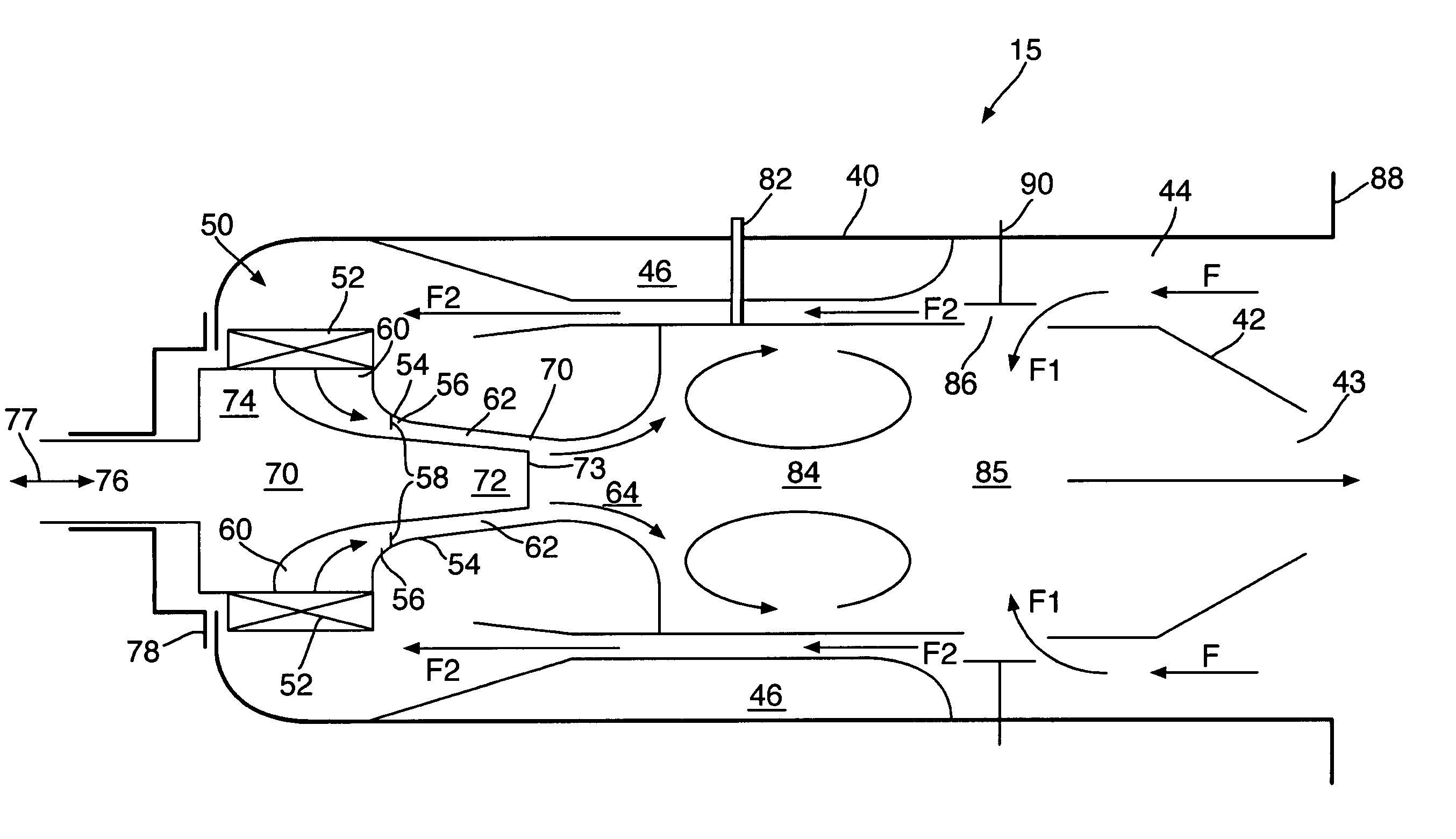
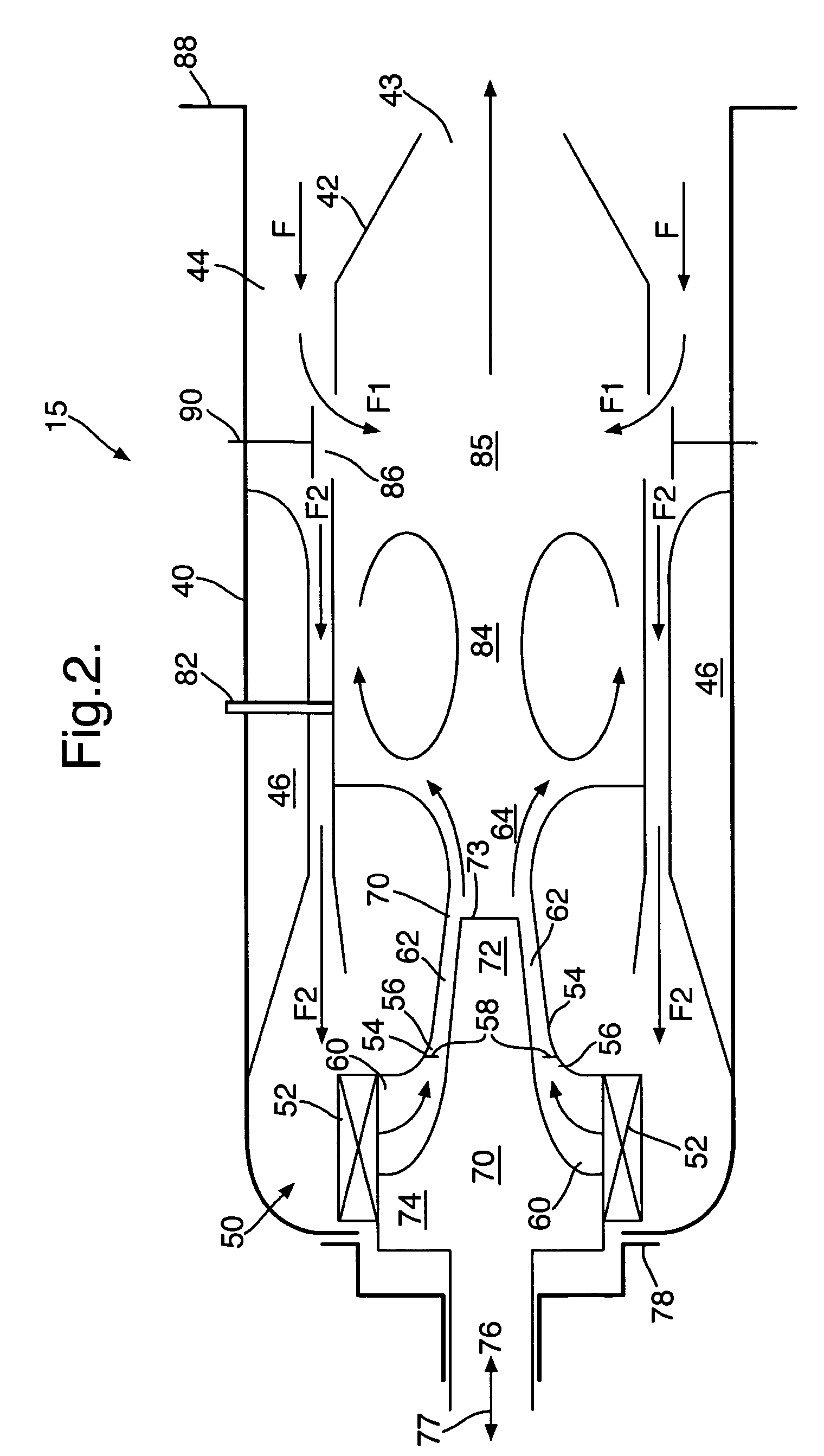
[0027]The figures illustrate a variable geometry combustor (15) comprising a combustor liner (42) defining at least one dilution port (86) for providing air to a dilution zone (85) of the combustor (15); and at least one valve (90) positioned adjacent the dilution port (86) for controlling the flow of air through the dilution port (86), the valve (90) being settable to maintain one of a plurality of different open configurations.

[0028]The figures also illustrate a variable geometry pre-mixing fuel injector (50) for injecting a fuel / air mix in a downstream direction, comprising: an air inlet (60); a fuel inlet (58) positioned downstream of the air inlet (60); a duct (56) extending at least downstream of the fuel inlet (58) to define a fuel and air pre-mixing zone (62), that narrows to form an opening (64); and means (70) for varying the flow of fuel / air mix from the pre-mixing zone (62) through the opening (64).

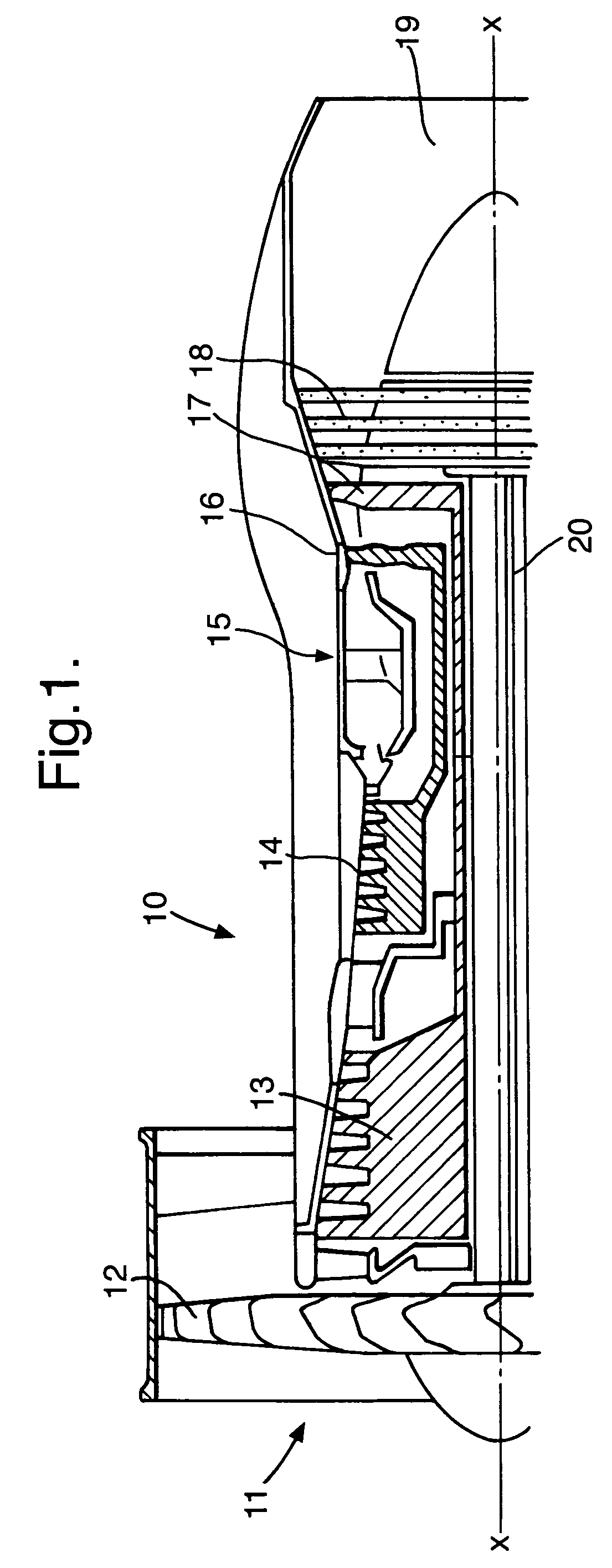
[0029]FIG. 1 illustrates a sectional side view of the upper half of a gas...


PUM


Abstract

A variable geometry pre-mixing fuel injector (50) for injecting a fuel / air mix in a downstream direction, comprising: an air inlet (60); a fuel inlet (58) positioned downstream of the air inlet (60); a duct (56) extending at least downstream of the fuel inlet (58) to define a fuel and air pre-mixing zone (62), that narrows to form an opening (64); and means for varying the flow of fuel / air mix from the pre-mixing zone (62) through the opening (64).

Description

FIELD OF THE INVENTION[0001]Embodiments of the present invention relate to a variable geometry pre-mixing fuel injector. Such a fuel injector may be used in a gas turbine engine.BACKGROUND OF THE INVENTION[0002]To achieve low emissions of undesirable combustion products for gas turbine engines, lean pre-mixed combustion systems are used. These systems have a pre-mixing zone for creating a controlled fuel / air mix, a reaction zone for combusting the fuel / air mix and a dilution zone for adding air to the combustion products.[0003]These types of combustion systems are sensitive to the fuel / air ratio produced at the pre-mixing zone. There is an optimum value of flame temperature for low NOx emissions. If the percentage of fuel increases beyond the optimum, then NOx emissions increase as the flame temperature increases. If the percentage of fuel decreases below the optimum then CO emissions increase and the combustor may go out because the flame temperature has fallen too low.[0004]A gas ...

Claims


Application Information

Patent Timeline
Patent Type & Authority Patents(United States)
IPC IPC(8): F23R3/26F23R3/30F23N1/02F23R3/28
CPCF23N1/022F23R3/26F23R3/286F23D2900/11402
Inventor SANDERS, NOEL A
Owner ROLLS ROYCE PLC
Learn More