Flow-based energy transport and generation device

a technology of energy transportation and generation devices, applied in the direction of energy industry, sustainable buildings, gas/liquid distribution and storage, etc., can solve the problems of enormous time and cost required to build this infrastructure before, and achieve the effect of maximizing the energy delivered

Inactive Publication Date: 2013-05-09
SHROSBREE CRAIG DOUGLAS
View PDF1 Cites 8 Cited by
  • Summary
  • Abstract
  • Description
  • Claims
  • Application Information

AI Technical Summary

Benefits of technology

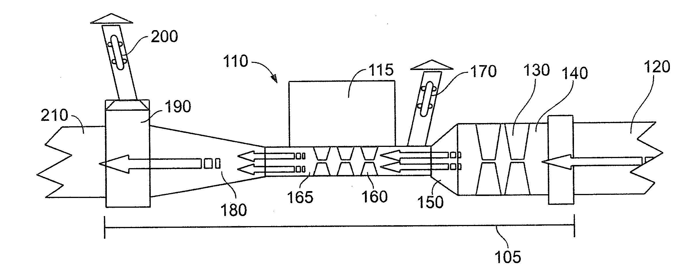
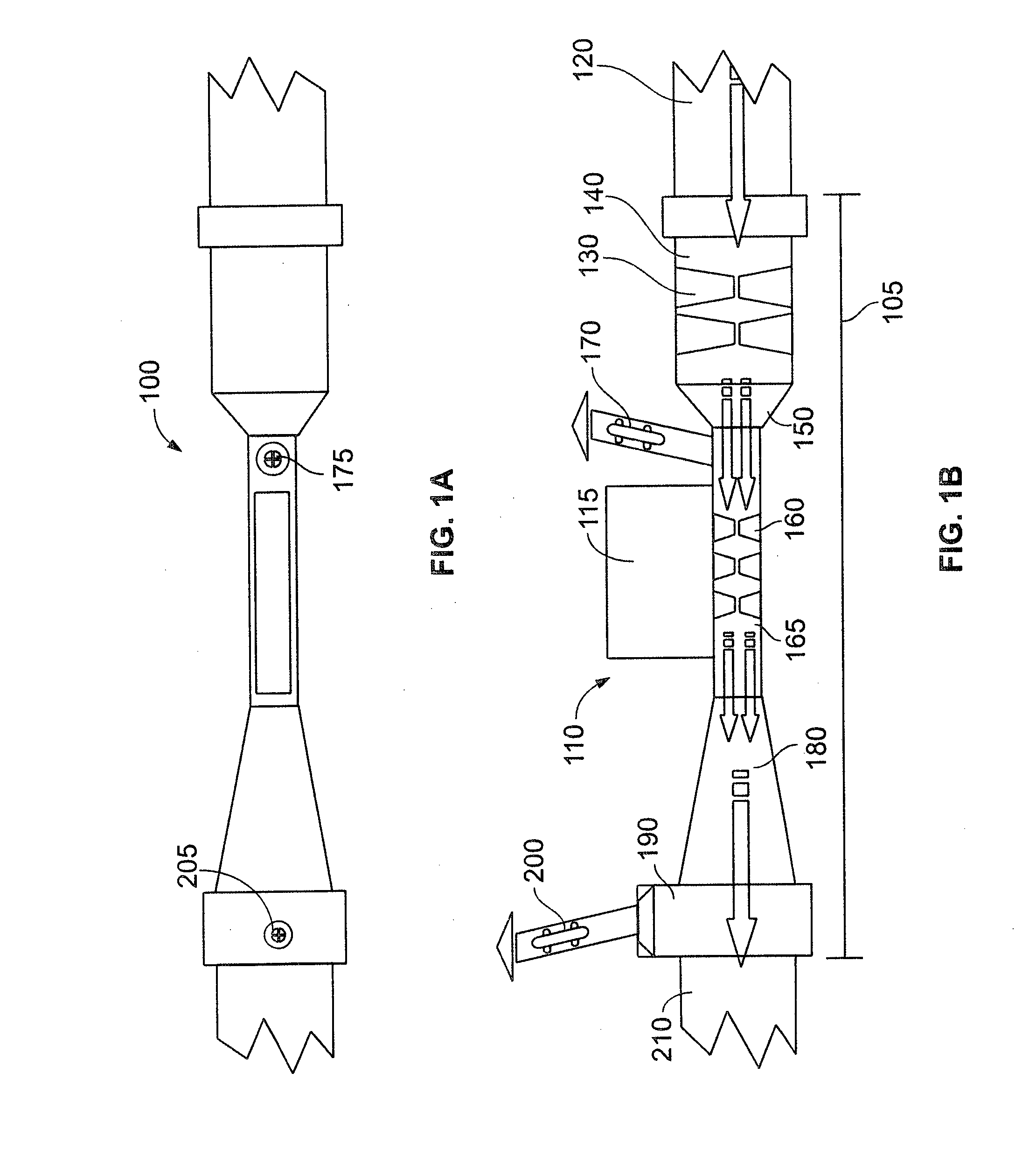
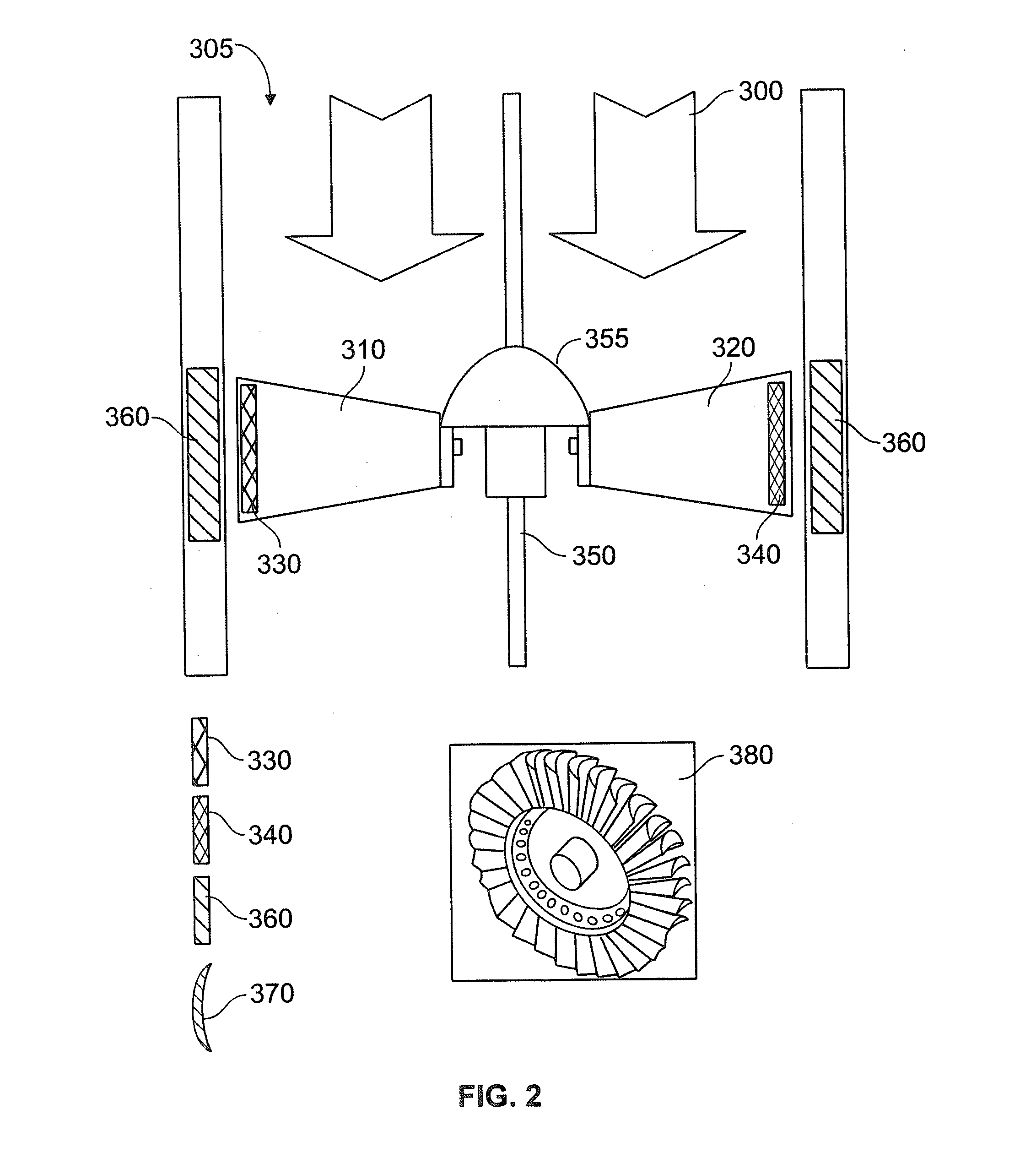
[0004]Embodiments of the present invention generally relate to energy delivery and energy generation systems. More particularly, embodiments employ existing fluid-delivery infrastructure for the transport and generation of energy. Aspects of the present invention allow energy used to create a fluid flow through a passageway to be partially recovered downstream. Further aspects of the present invention incorporate the use of one or more specially configured turbines to maximize the energy delivered by the system.

Problems solved by technology

In areas lacking the infrastructure to transport energy, enormous time and cost is required to build this infrastructure before any energy transfer can occur.

Method used


Image

  • Flow-based energy transport and generation device
  • Flow-based energy transport and generation device
  • Flow-based energy transport and generation device

Examples


Embodiment Construction

[0017]Devices for transporting and recovering energy utilizing the flow of a fluid are disclosed herein. The flowing fluid, such as water in a water main, can be used to generate energy, such as electricity, by directing the fluid through a specially configured passageway.

[0018]Various types of fluid flow may be generated. For example, a pumping station may be used to draw water from a natural source, such as a lake, and generate a fluid flow in water pipes for a municipal water system. As another example, fluid flow in a natural body of water, such as a stream, may be generated by rain water delivered to elevated regions. Also, water movement caused by tidal forces can be utilized in estuary locations. In the first example above, the pumping station uses energy from a power plant to move the water and impart the water with kinetic energy. In the second example, the potential energy of the rain water in the elevated regions is converted into kinetic energy as gravity acts on the rai...


PUM


Abstract

Energy used to create a fluid flow through a passageway, e.g., a municipal water system, is partially recovered downstream, e.g., at a residential location. An example energy system includes a primary passageway receiving a first fluid from an external source. The primary passageway includes a first region having a first cross sectional area and a second region having a second cross sectional area. The second cross sectional area is different than the first cross sectional area. The first fluid moves from the first region to the second region. A secondary passageway extends from the second region. A turbine is disposed in the secondary passageway. The movement of the first fluid through the primary passageway causes a movement of a second fluid in the secondary passageway, and the movement of the second fluid in the secondary passageway drives the turbine to generate energy.

Description

CROSS REFERENCE TO RELATED APPLICATIONS[0001]This application claims priority to U.S. Provisional Patent Application No. 61 / 331,321, filed May 4, 2010, the contents of which are incorporated entirely herein by reference.FIELD OF THE INVENTION[0002]The present invention generally relates to energy delivery and energy generation systems. More particularly, the invention employs existing fluid-delivery infrastructure for the transport of energy. The invention allows energy used to create a fluid flow through a passageway to be partially recovered downstream. The invention incorporates the use of one or more specially configured turbines to maximize the energy delivered by the system.BACKGROUND OF THE INVENTION[0003]Energy transportation is of great importance as significant infrastructure (e.g., a power grid) is often required to transport energy from an energy source, such as a power plant, to where the energy is required, such as a residential home. In areas lacking the infrastructur...

Claims


Application Information

Patent Timeline
Patent Type & Authority Applications(United States)
IPC IPC(8): F17D1/08
CPCF03D1/00F05B2220/602Y02E10/725Y02B10/70F17D1/08Y02B10/30Y02E10/72Y02P80/10
Inventor SHROSBREE, CRAIG DOUGLAS
Owner SHROSBREE CRAIG DOUGLAS
Why Eureka
Try Eureka