Motor

Active Publication Date: 2013-05-09
PANASONIC CORP
View PDF6 Cites 19 Cited by
  • Summary
  • Abstract
  • Description
  • Claims
  • Application Information

AI Technical Summary

Benefits of technology

The patent text describes a structure for a motor that increases the efficiency and resistance to demagnetization of the permanent magnet. This is achieved by arranging the salient poles in a way that increases the likelihood of aligning with the magnetic circuit of the permanent magnet and maximizing the permeance coefficient. The structure also reduces the time period when the salient poles are not in the magnetic circuit, resulting in high torque production.

Problems solved by technology

However, this structure of the motor 101 has a problem.
This reduces magnetic fluxes to be flowed to the rotor 108, and as a result cannot sufficiently improve torque to be produced by the rotor 108.

Method used


Image

  • Motor
  • Motor
  • Motor

Examples


embodiment 1

Structure

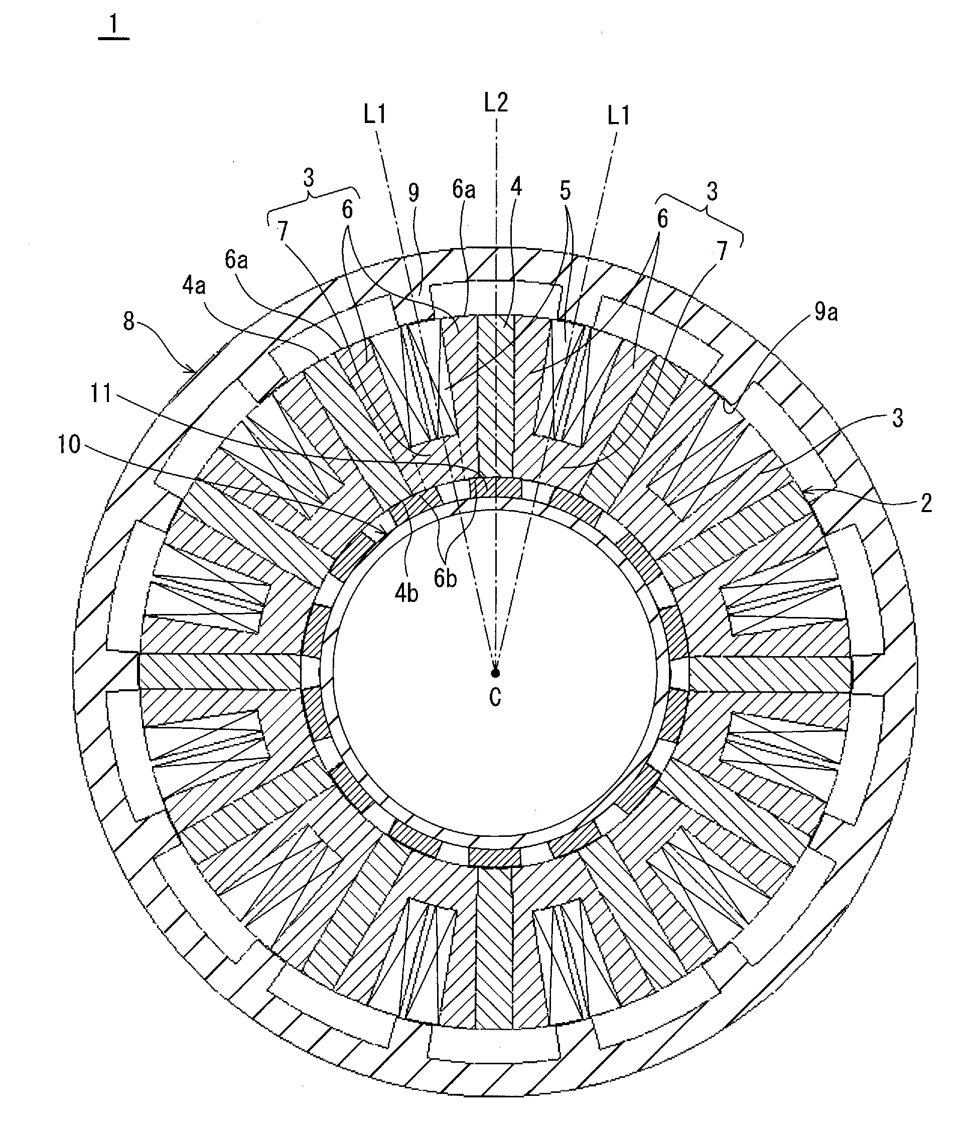
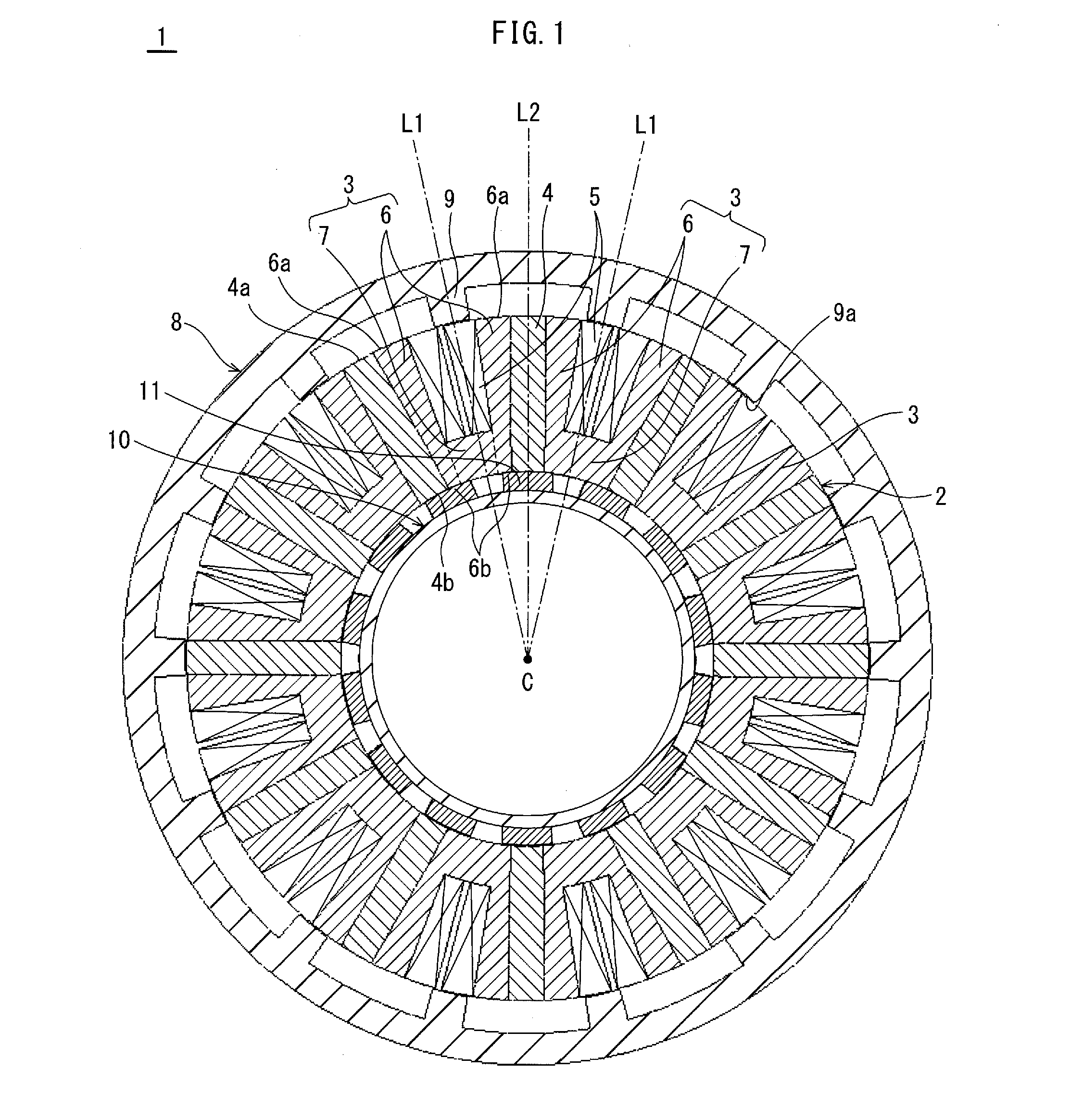
[0073]FIG. 1 shows the structure of a motor relating to the present embodiment.

[0074]The motor 1 includes an annular stator 2, an annular outer-rotor 8, and an annular inner-rotor 10. The outer-rotor 8 is arranged outside the stator 2, and has the rotational axis coincident with the central axis of the stator 2. The inner-rotor 10 is arranged inside the stator 2, and has the rotational axis coincident with the central axis of the stator 2 so as to be coupled to the outer-rotor 8 via a shaft to rotate in conjunction with the outer-rotor 8. The stator 2 includes 12 permanent magnets 4 arranged at regular spaced intervals in a circumferential direction thereof, a plurality of stator cores 3 (12 stator cores in the example shown in FIG. 1) that are each arranged between two adjacent permanent magnets 4, and 12 coils 5.

[0075]The outer-rotor 8 and the inner-rotor 10 are each made of a soft magnetic material. Also, the outer-rotor 8 has 14 first salient poles 9 each projecting in...

embodiment 2

[0108]FIG. 8 shows the structure of a motor 21 relating to the present embodiment.

[0109]The motor 21 includes an annular stator 22, an annular outer-rotor 30, and an annular inner-rotor 28. The outer-rotor 30 is arranged outside the stator 22, and has the rotational axis coincident with the central axis of the stator 22. The inner-rotor 28 is arranged inside the stator 22, and has the rotational axis coincident with the central axis of the stator 22 so as to rotate in conjunction with the outer-rotor 30. The stator 2 includes 12 permanent magnets 24 arranged at regular spaced intervals in a circumferential direction thereof, 12 stator cores 23 that are each arranged between two adjacent permanent magnets 24, and 12 coils 25. In the following, with respect to the structure that is the same as that relating to Embodiment 1, description thereof is appropriately omitted.

[0110]The outer-rotor 30 has 10 first salient poles 31 each projecting inward, and the inner-rotor 28 has 10 second sa...


PUM


Abstract

To provide a motor including: an annular stator including permanent magnets and stator cores that are alternately arranged circumferentially, and coils; an annular outer-rotor being arranged outside the stator, having a rotational axis coincident with a central axis of the stator, and having first salient poles; and an annular inner-rotor being arranged inside the stator, having a rotational axis coincident with the central axis to rotate in conjunction with the outer-rotor, and having second salient poles equal in number to the first salient poles, the magnets are magnetized circumferentially and extend radially, and each have respective ends that are opened toward the outer-rotor and toward inner-rotor in the radial direction, the coils are each wound by concentrated-winding on a tooth constituted from a different one magnet and respective parts of two stator cores adjacent to the magnet, and the first and second salient poles are arranged at offset positions circumferentially.

Description

TECHNICAL FIELD[0001]The present invention relates to a motor with use of permanent magnets.BACKGROUND ART[0002]There is a particular desire for motors for use in compressors, electric cars, hybrid cars, fuel cell-powered cars, and the like to produce high torque, among the demands for motors to be small, light-weight, high-output, low-vibration, low-noise, and high-efficient.[0003]In response to the above demand, there has conventionally been proposed a motor 101 as shown in FIG. 18 (see Patent Literature 1). The motor 101 includes an annular stator 102 that includes stator cores 103, permanent magnets 104, and coils 105, and a rotor 108 having a plurality of salient poles 109 (five salient poles in FIG. 18). The stator cores 103 have a plurality of teeth 110 (six teeth in FIG. 18) and an annular stator yoke 107 surrounding the outer side of each of the teeth 110. The motor 101 improves torque with use of magnetic fluxes generated by the permanent magnets 104.[0004]However, this st...

Claims


Application Information

Patent Timeline
IPC IPC(8): H02K21/04H02K16/02
CPCH02K21/44H02K21/04H02K16/02
Inventor NISHIYAMA, NORIYOSHI
Owner PANASONIC CORP
Why Eureka
Try Eureka