
Modular sprag clutch cage

Inactive Publication Date: 2013-05-16
SCHAEFFLER TECH AG & CO KG
View PDF5 Cites 7 Cited by
  • Summary
  • Abstract
  • Description
  • Claims
  • Application Information

AI Technical Summary

Benefits of technology

The present invention is a cage for a one-way clutch that is made up of individual interlocking links. The cage can accommodate a variety of shaft diameters by adjusting the number of links used. The cage allows for the incorporation of sprags and / or load bearing rollers to act on the raceways, which simplifies clutch design, reduces friction, and narrows the overall assembly width of the cage. The ratio of cage links containing rollers to sprags can be adjusted depending on the application. The technical effects of this invention are that it reduces tooling and assembly costs, while providing efficient and compact support for a variety of shaft diameters.

Problems solved by technology

The tooling costs associated with the production of a one-piece cage are usually a large initial investment.
Thus, the tooling cost associated with the production of cages for one-way clutches arranged on different shaft and outer ring diameters can require a large initial investment as separate dedicated tooling is required to produce cages for different shaft and outer ring diameters.
Also, the spring(s) used in existing one-way cages add to the expense of the cage because the springs are expensive, require separate assembly, are difficult to install in the cage, and require separate inspection.
However, centering washers add to the expense and the complexity of a clutch assembly as the centering washer has narrow tolerances for accurately centering the shaft in an outer race.
However, the alloys and tight tolerances required make the centering washers expensive.
Furthermore, the centering washer(s) is placed alongside the one-way clutch cage, which adds to the overall axial space requirement of the one-way clutch.

Method used


Image

  • Modular sprag clutch cage
  • Modular sprag clutch cage
  • Modular sprag clutch cage

Examples


first embodiment

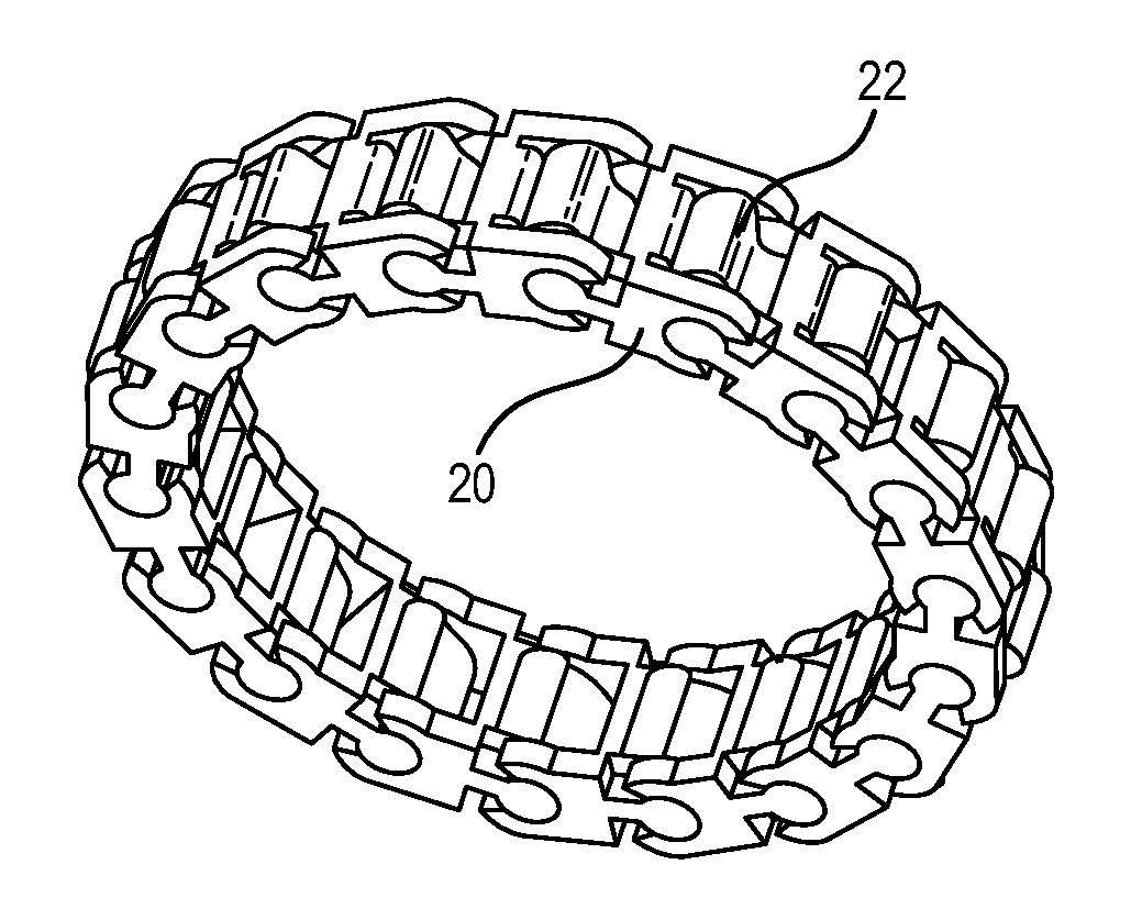
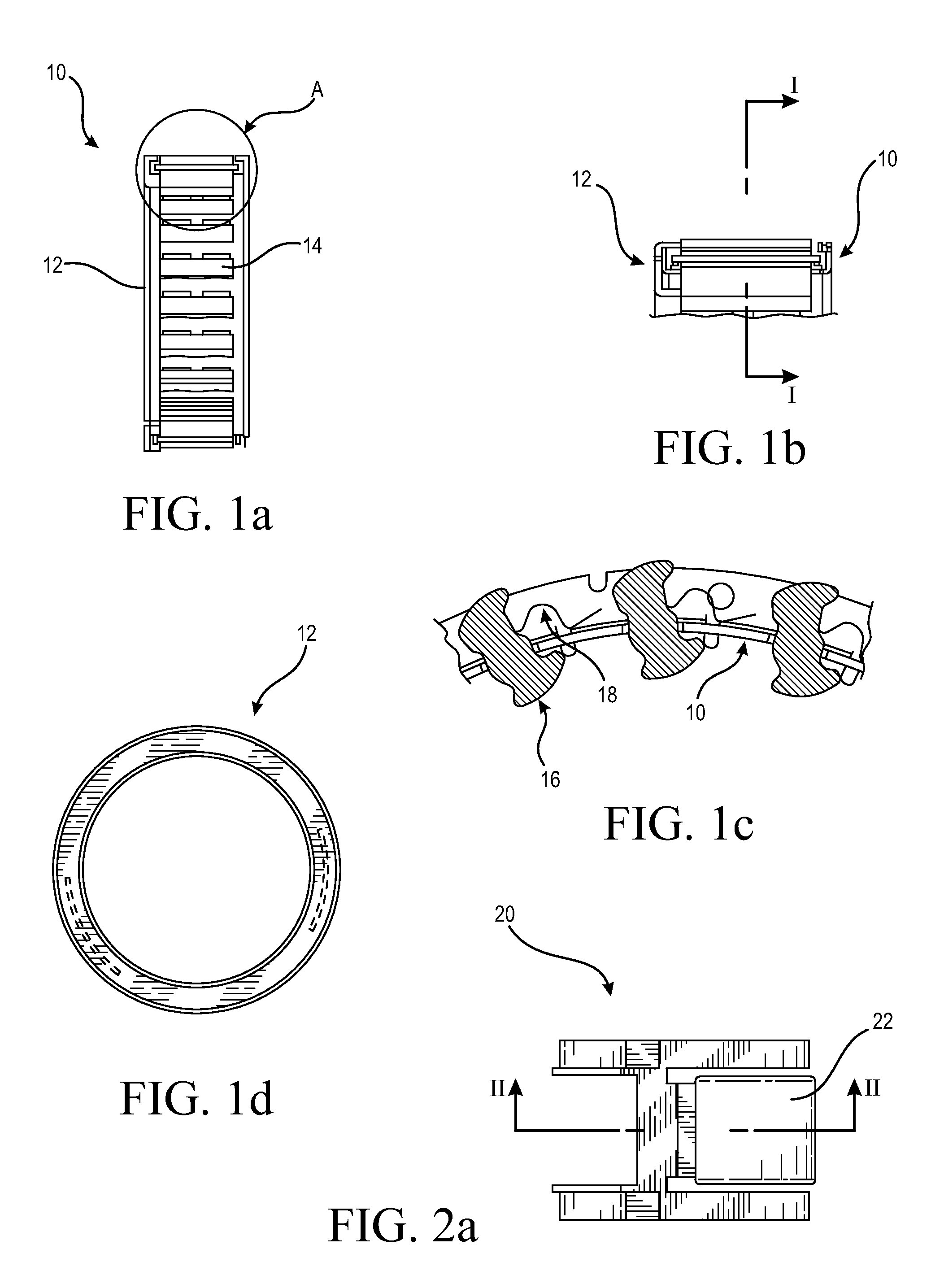
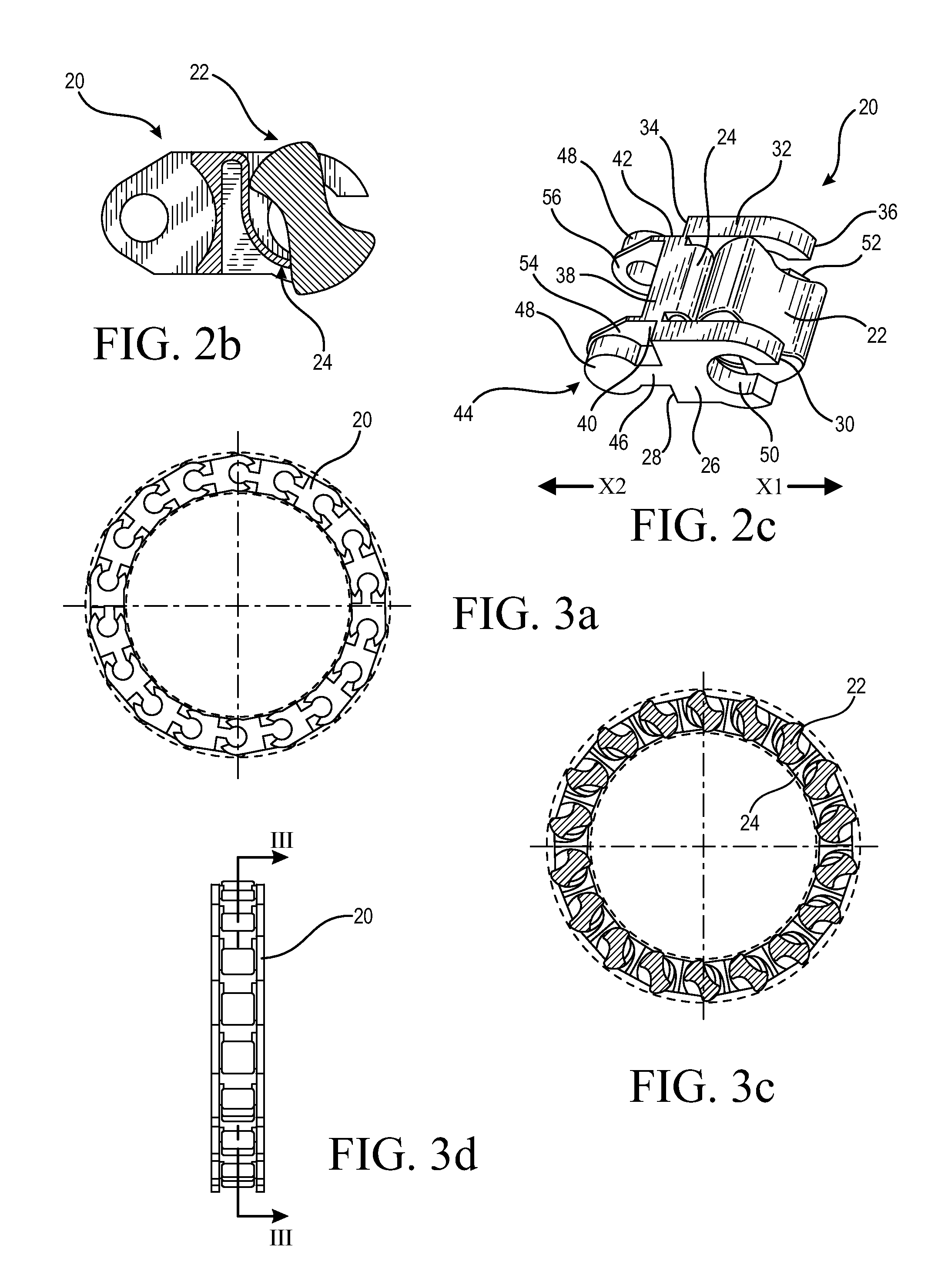
[0030]FIG. 2a is a top view of a cage link 20 of the present invention, which is intended for use with a sprag 22. FIG. 2b is a cross-sectional view along the line II-II in FIG. 2a of the cage link 20 with the sprag 22 arranged therein. In FIG. 2b, the cage link 20 has a spring element 24, which is molded integral to the cage link 20. The spring element 24 extends in a curved manner from the cage link 20 to provide a sloped surface for the sprag 22 to rotate against. However, any known spring shape can be used. The spring element 24 imparts a force on the sprag 22 to bias the sprag 22. Alternatively, the spring element does not have to be molded integral to the cage link 20 and the spring element can be a metal spring.

[0031]FIG. 2c is a perspective view of the cage link 20 with the sprag 22 arranged therein. The cage link 20 has a substantially U-shaped opening formed form a first sidewall 26, which has a first end 28 and a second end 30, a second sidewall 32, which has a first end ...

second embodiment

[0034]FIG. 5a is a top view of a cage link 58 of the present invention, which is intended for us with a roller 60. FIG. 5b is a cross-sectional view along line IV-IV in FIG. 5a of the cage link 58 with the roller 60 arranged within the cage link 58. In FIGS. 5a and 5b, the cage link 58 has a spring element 62 molded integral to the cage link 58. Alternatively, the spring element does not have to be molded integral to the cage link 58 and the spring element can be a metal spring. FIG. 5c is a perspective view of the cage link 58 with the roller 60 arranged within the cage link 58. The cage links 58 for rollers 60 are intended to be combined with cage links 20 for sprags 22. As such, the cage links 58 for rollers 60 and the cage links 20 for sprags 22 can be structurally identical with the exception being the integration of the spring element 24 or 62. As shown in FIG. 5c, the spring element 62 is formed integral with the cage link 58 and has a semi-circular shape to at least partiall...


PUM

PropertyMeasurementUnit
Diameteraaaaaaaaaa

Abstract

A cage for a one-way clutch that is made of individual interlocking links. The cage links forms a continuous chain which is arranged on a shaft and housed within an associated outer ring. The cage links have connecting members and receiving grooves. The connecting members of one cage link are snapped into the receiving grooves of another cage link to form the continuous chain for different diameters. Sprags and / or load bearing rollers, along with spring elements, are arranged within each cage link.

Description

CROSS-REFERENCE TO RELATED APPLICATIONS[0001]This application claims the priority of U.S. 61 / 559,905 filed Nov. 15, 2011, which is incorporated by reference herein.FIELD OF INVENTION[0002]The present invention relates generally to clutches and more particularly to a cage comprised of individual interconnected cage links for one-way clutches.BACKGROUND OF THE INVENTION[0003]Typically, one-way clutches, which freewheel in one rotational direction and transmit torque in the other direction, utilize cages to hold sprags or rollers. One-way clutches are used for a wide variety of applications including industrial power transmission equipment, automobile transmissions, torque converters, material handling equipment, and manufacturing equipment. Regularly, one-way clutches are arranged on a shaft of the application and include an outer ring. Depending on the application, the cage can be applied directly onto the shaft or the cage can also include an inner ring. The cages used in known one-...

Claims


Application Information

Patent Timeline
IPC IPC(8): F16D15/00
CPCF16D15/00Y10T29/49876F16D41/07
Inventor NELSON, ERIC S.
Owner SCHAEFFLER TECH AG & CO KG
Learn More