

Contactless radial position sensor having improved response behavior to target defects
- Summary
- Abstract
- Description
- Claims
- Application Information
AI Technical Summary
Benefits of technology
Problems solved by technology
Method used
Image

Examples
first embodiment
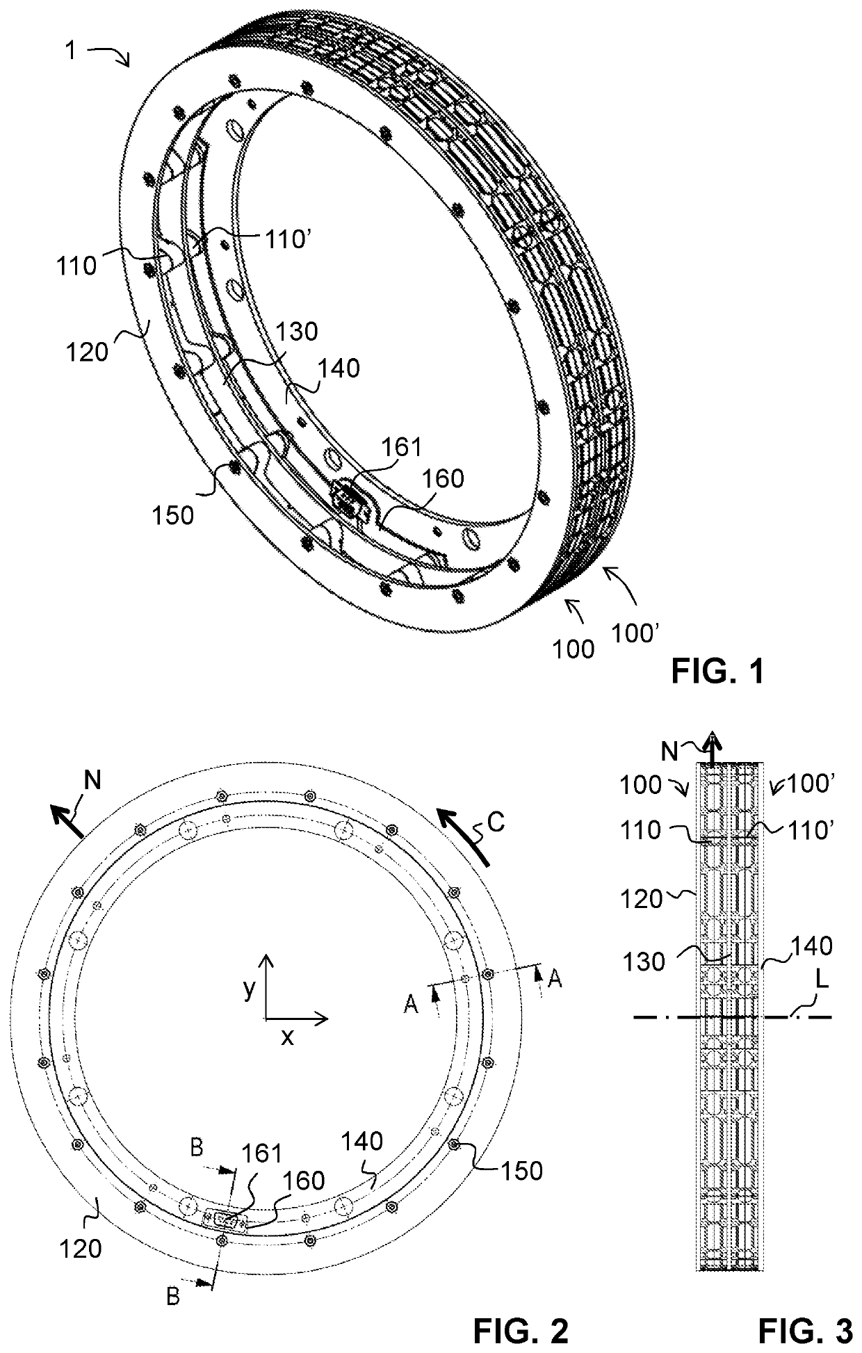
[0072]A transducer assembly 1 according to a first embodiment of the present invention is illustrated in FIGS. 1-5. The transducer assembly 1 is configured to determine the radial position of a hollow external rotor (not illustrated in FIGS. 1-5) that radially surrounds the transducer assembly 1. Accordingly, the transducer assembly 1 is configured to interact with target surfaces on the inner circumference of the hollow rotor.
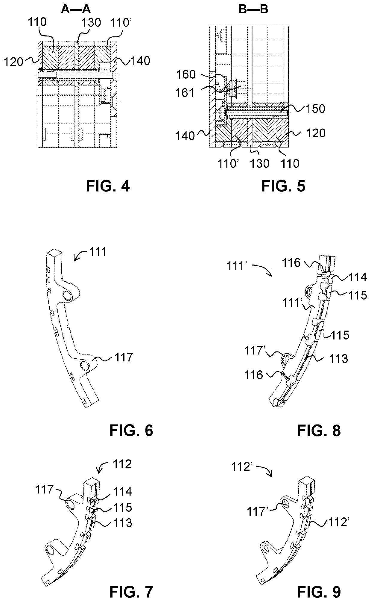
[0073]The transducer assembly 1 comprises a first transducer 100 and a second transducer 100′. Each transducer 100, 100′ comprises an annular coil support 110, 110′. The annular coil supports 110, 110′ define a common longitudinal axis L (FIG. 3). At the one axial end, the transducer assembly 1 comprises an electrically conducting annular bottom plate 120. The transducers 100, 100′ are separated by an electrically conducting shielding ring 130. At its other axial end, the transducer assembly comprises an electrically conducting annular top plate 140. Between t...
second embodiment
[0103]FIG. 16 illustrates a transducer unit 1′ according to a second embodiment of the present invention. The transducer unit 1′ of the second embodiment is very similar to the transducer unit 1 of the first embodiment. However, the outer circumference of second transducer 100′ is covered by an annular, metallic reference target 180 disposed at a fixed radial distance from the first and second coils of the second transducer 100′. In order to accommodate the reference target 180, the coil support of the second transducer has a slightly reduced outer diameter as compared to the coil support of the first transducer.
[0104]A possible application that employs the transducer unit 1′ of the second embodiment is illustrated in a highly schematic manner in FIG. 17. Like components are designated with the same reference numerals as in FIG. 15. Again, rotor 300 is illustrated as an internal rotor for simplicity, while it may as well be an external rotor. In this embodiment, coil 170 of the firs...
third embodiment
[0107]A transducer according to a third embodiment will be described with reference to FIG. 18. While the first and second embodiments are designed to interact with an external rotor, the third embodiment is designed for an internal rotor.
[0108]Generally speaking, it is easier to implement the present invention for an external rotor. In this case, the coils interact radially outwardly with the target. The coils can be arranged in the slots from outside and will be held by the hooks of the coil support without any further measures. This is not the case when the transducer is designed to interact with an internal rotor. In this case, specific measures need to be taken to avoid that the coils fall inside and touch the internal rotor. It is therefore proposed to also mount the coils to a coil support from outside, similar to the first and second embodiments. The coils are then filled with resin, and the coil support is turned from the inside until only a thin membrane remains between th...
PUM
 Abstract
Description
Claims
Application Information