
Cooled vane of a high-pressure turbine

Active Publication Date: 2015-08-27
SN DETUDE & DE CONSTR DE MOTEURS DAVIATION S N E C M A
View PDF10 Cites 5 Cited by
  • Summary
  • Abstract
  • Description
  • Claims
  • Application Information

AI Technical Summary

Benefits of technology

The patent aims to prevent gas from leaking between two parts called tenon and mortise. This is achieved by creating a connection between the tenon and the mortise wall that forms a solid barrier. This results in a more effective and reliable connection between the two parts.

Problems solved by technology

This method of connecting by brazing is well known but requires expensive operations relating to the need for a furnace, which operations it would be desirable to reduce.
However, it will be noted that the transparent welding is likely to cause the appearance of cracks in the vane root.
These cracks can spread and damage the part.
However, this solution would lead to the elimination of the seals and the risk of causing leaks of calibrated air between the different cavities of the cooling circuit.

Method used


Image

  • Cooled vane of a high-pressure turbine
  • Cooled vane of a high-pressure turbine
  • Cooled vane of a high-pressure turbine

Examples


Embodiment Construction

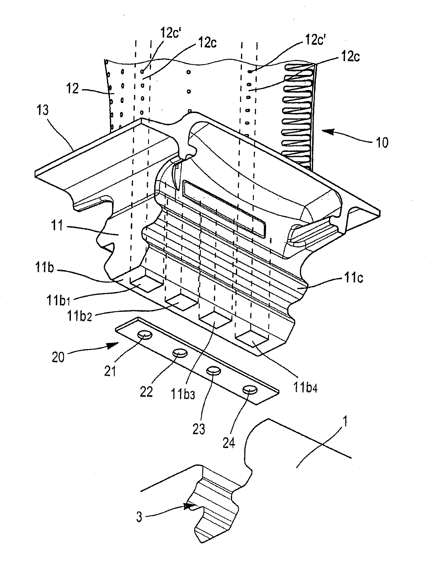
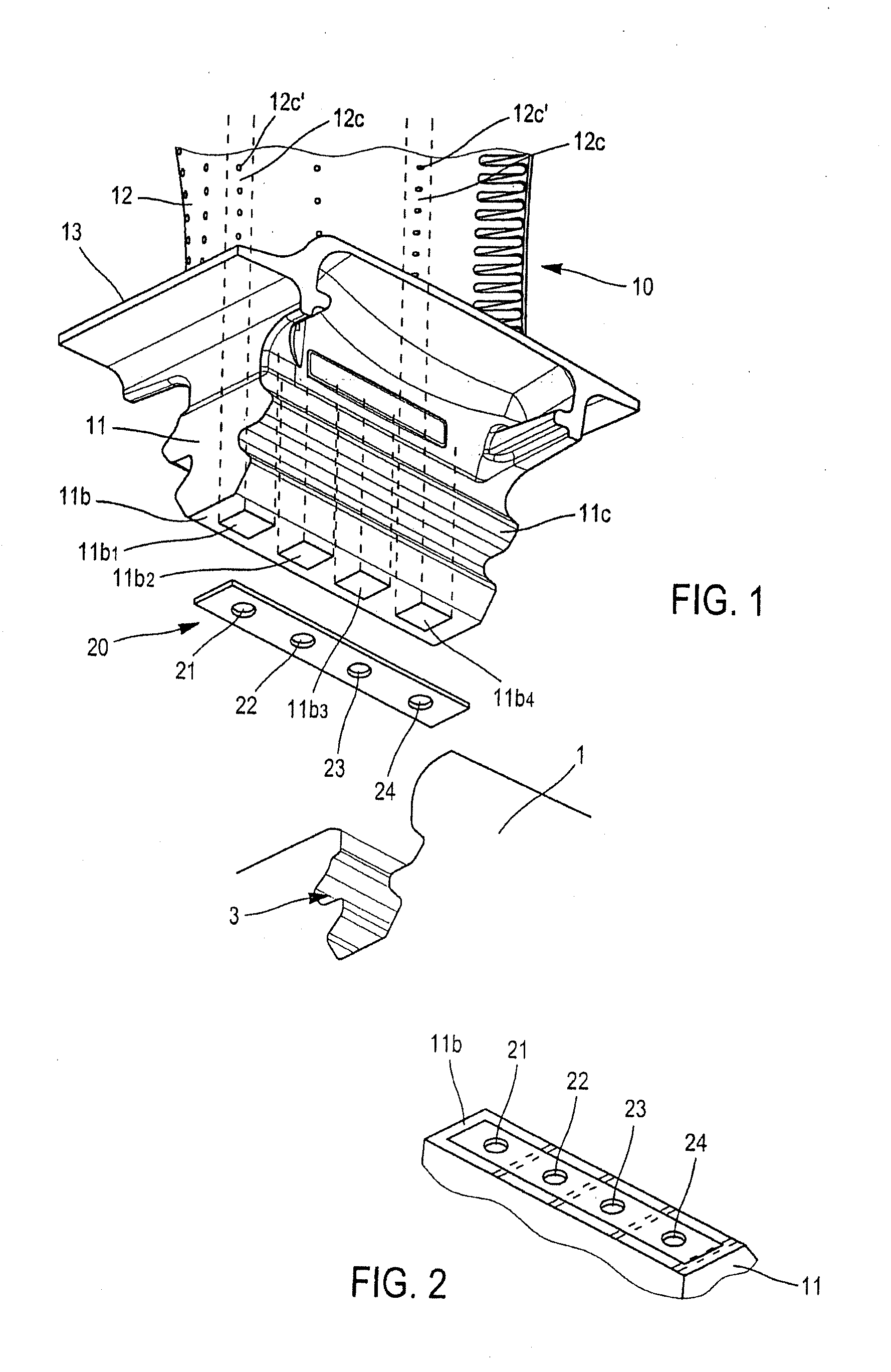
[0032]A rotor of an axial, high-pressure turbine comprises a disc 1 and a plurality of vanes 10 which are attached radially to the rim thereof. The vanes comprise a root 11, a blade 12 and a platform 13 between the root and the blade 12. The vanes are lodged by their root in axial recesses 3 machined in the rim of the disc 1. The root 11 and the sides of the recess are shaped, the section here said to have the shape of a fir tree, in such a way as to hold and ensure the retention of the vane in the recess thereof when the disc 20 is driven in rotation about its axis. The blade 12 of aerodynamic form extends radially over the height of the gas stream, and the platform arranged transversely in relation to the axis of the vane forms a radially inner wall element of the stream. The vane is cooled in order to ensure resistance to the high temperatures of the gas engine. The vane is hollow with a plurality of inner cavities in which the cooling air circulates. To this end and according to...


PUM


Abstract

The invention relates to a movable vane of a turbomachine comprising a blade (12) with inner cooling cavities and a root (11) by which means the vane can be mounted on a rotor disk, the root comprising at least two channels (11a) communicating with said inner cavities and leading to the base (11b) thereof, said base comprising at least two openings (11b1, 11b2) through which the channels open up, and a calibrating plate (20) provided with calibrated perforations (21, 22) corresponding to said openings being attached to the base (11b) of the root. The vane is characterised in that a mechanical means (25, 26; 11m1, 11m2) forming a sealing barrier between the two openings is arranged between the plate and the base of the root.

Description

TECHNICAL FIELD[0001]The present invention relates to the field of turbine engines and concerns a turbine vane cooled by means of a coolant, said coolant circulating internally.PRIOR ART[0002]A turbine engine is a rotating machine in which a transfer of energy occurs between the flow of a fluid and a system of vanes which are rigidly connected to a rotor, for example a compressor or a turbine forming part of a turboshaft engine such as a gas turbine engine. A gas turbine turboshaft engine for an aircraft, such as a multi-flow turbojet engine, generally comprises, from upstream to downstream in the direction of flow of the gases, a fan, one or more compressor stages, for example a low-pressure compressor and a high-pressure compressor, a combustion chamber, one or more turbine stages, for example a high-pressure turbine and a low-pressure turbine, and a gas exhaust pipe. A turbine can correspond to each compressor, the two being connected by a shaft, thus forming, for example, a high...

Claims


Application Information

Patent Timeline
IPC IPC(8): F01D5/18F01D5/08
CPCF01D5/186F01D5/085F05D2220/32F05D2230/237F05D2240/55F01D5/081F01D5/18Y02T50/60
Inventor BOTREL, ERWAN DANIELDUJOL, CHARLOTTE, MARIE
Owner SN DETUDE & DE CONSTR DE MOTEURS DAVIATION S N E C M A
Learn More