Supercharge Your Innovation With Domain-Expert AI Agents!

Transmission line apparatus

Inactive Publication Date: 2007-03-15
PANASONIC CORP
View PDF2 Cites 3 Cited by
  • Summary
  • Abstract
  • Description
  • Claims
  • Application Information

AI Technical Summary

Benefits of technology

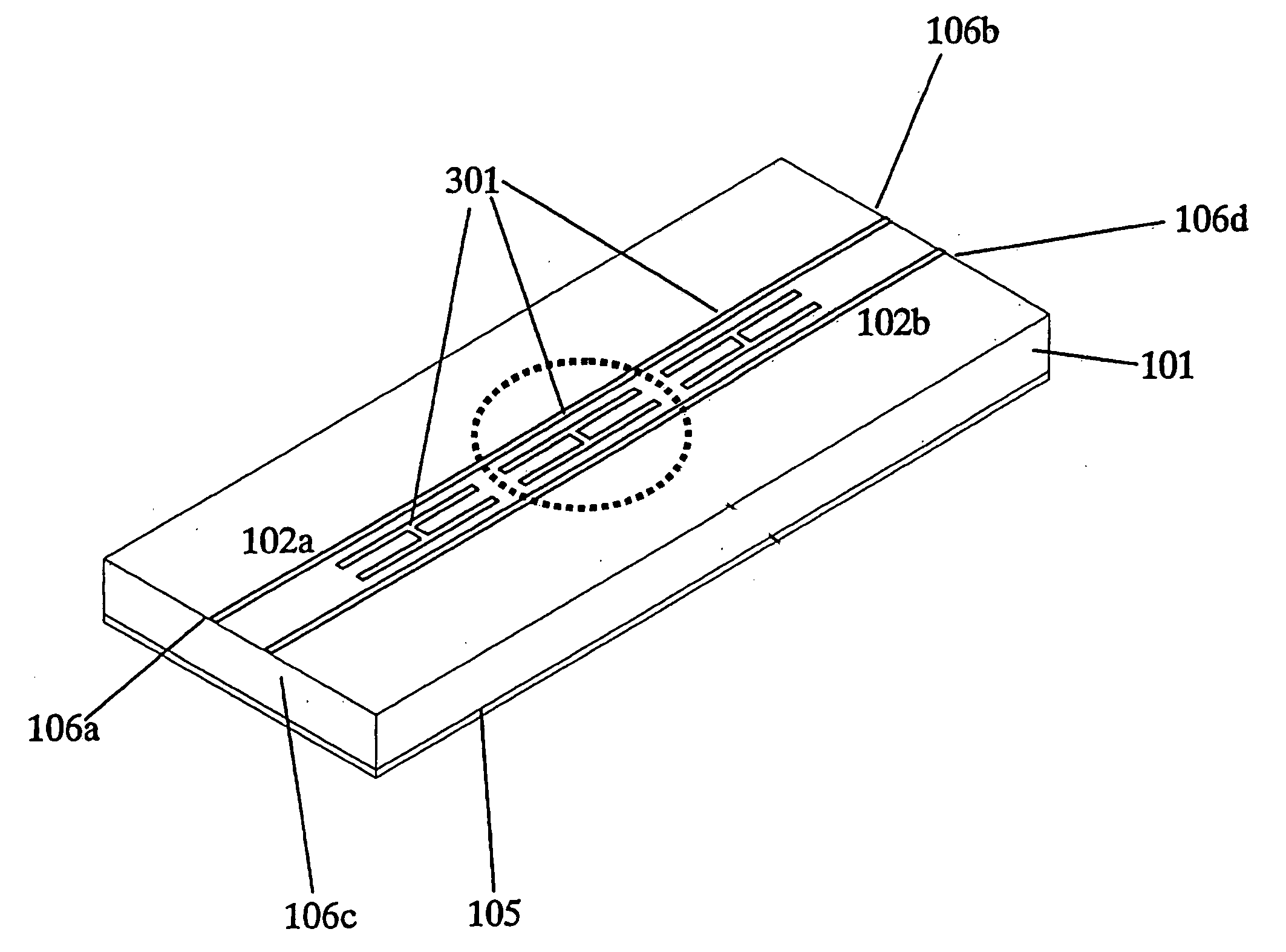
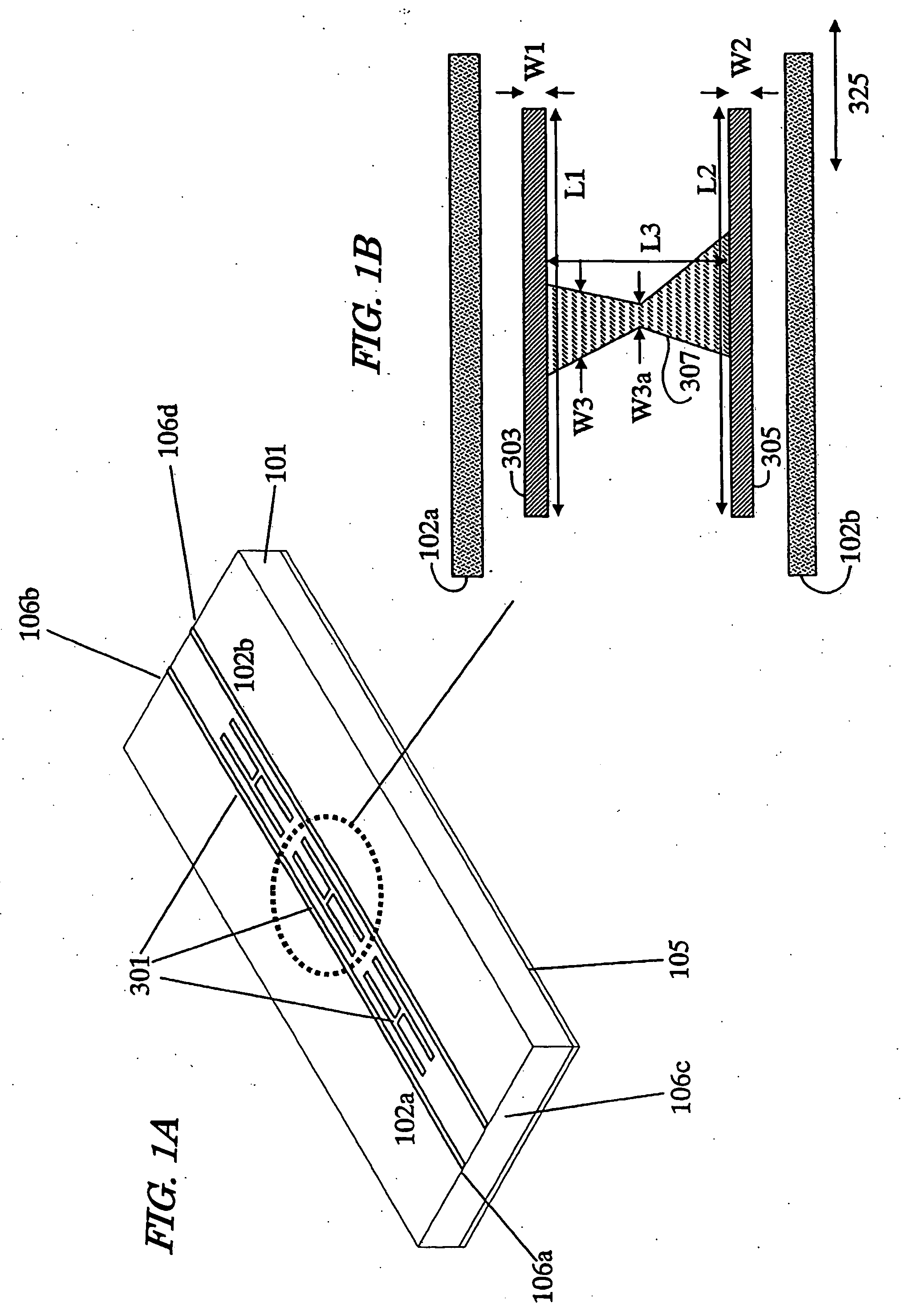
[0031] A transmission line apparatus according to the present invention adopts an additional capacitance element with a novel structure that can reduce ground capacitance instead of the additional capacitance element that cannot suppress the crosstalk sufficiently in the conventional transmission line apparatus. As a result, the crosstalk can be actually suppressed effectively.
[0032] In addition, according to the present invention, the additional capacitance element can be arranged as an integrated element, not as a chip component. Consequently, a transmission line apparatus that is advantageous in terms of cost, circuit capacity and performance is realized with no need to consider any variation between chip components during the design process.
[0033] Furthermore, according to the present invention, the deterioration in the transmission characteristic of signals can also be reduced compared to the method of reducing the crosstalk by bringing the lines closer to each other with the line widths increased locally as adopted in the conventional transmission line apparatus.

Problems solved by technology

As a result, crosstalk will often occur between the adjacent transmission lines, thus causing the problem of a decreased degree of isolation.
Those conventional pairs of transmission lines that are specially designed to suppress the crosstalk, however, have the following three problems, for example, and are actually unable to suppress the crosstalk effectively.
Firstly, Configuration Example No. 1 of Japanese Patent Application Laid-Open Publication No. 2001-257509 needs additional external circuit components in capacitors, thus requiring increased component and assembling costs.
The crosstalk suppressing components disclosed in Japanese Patent Application Laid-Open Publication No. 2004-015534 also have a similar problem.
In an actual circuit, however, it is difficult to improve that characteristic.
Thirdly, according to a method of increasing the mutual capacitance between the signal lines by locally increasing the line widths of the signal lines as disclosed in Japanese Patent Application Laid-Open Publication No. 2001-257509, the characteristic impedances of the lines change, thus deteriorating the transmission characteristic.

Method used


Image

  • Transmission line apparatus
  • Transmission line apparatus
  • Transmission line apparatus

Examples


examples

[0104] Transmission wiring circuit structures were made as samples representing specific examples of the present invention and Prior Art Examples by using a dielectric substrate with a dielectric constant of three and a total thickness of 150 μm as a circuit board. The entire back surface of the substrate was turned into a conductor by covering the back surface with copper wiring with a thickness of 40 μm. In this manner, a ground conductor was formed on the back surface. The principal surface of the substrate was also turned into a conductor with copper wiring with a thickness of 40 μm and then the conductor was partially removed by a wet etching process, thereby forming a pattern there.

[0105] To achieve a characteristic impedance of 50 Ω, two microstrip lines, in which the signal strips had a line width of 350 μm, were arranged parallel to each other as first and second transmission lines of a single-ended signal transmission system. And the crosstalk characteristic between the t...


PUM


Abstract

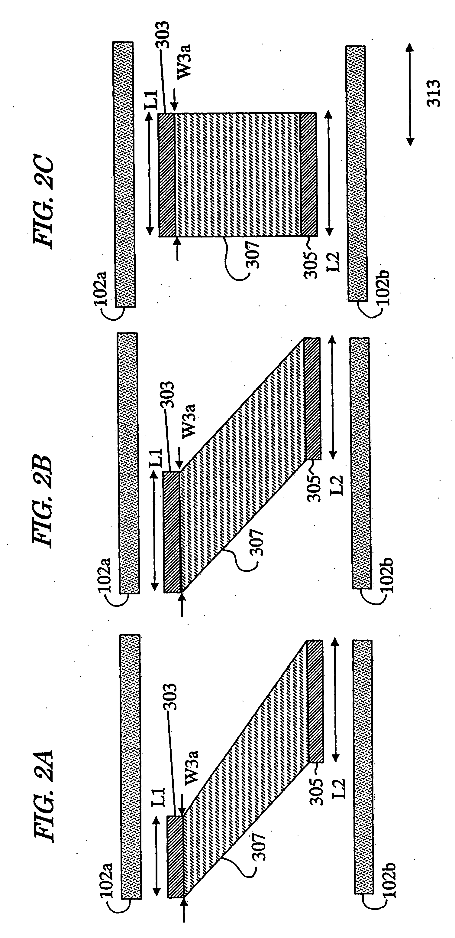
A transmission line apparatus includes: a substrate 101 with a ground conductor plane; and first and second signal strips 102a, 102b supported on the substrate 101 in parallel with each other. The apparatus further includes at least one additional capacitance element 301 that connects the first and second signal strips 102a, 102b together. The element 301 includes: a first additional conductor 303 spaced from the first signal strip 102a; a second additional conductor 305 spaced from the second signal strip 102b; and a third additional conductor 307 connected to the first and second additional conductors 303, 305 at respective points. When measured in a signal transmission direction, the smallest width W3a of the third additional conductor 307 is shorter than the length L1 or L2 of the first or second additional conductor 303 or 305. And the additional capacitance element 301 has a resonant frequency that is higher than the frequency of a signal being transmitted.

Description

[0001] This is a continuation of International Application No. PCT / JP2006 / 311759, with an international filing date of Jun. 12, 2006, which claims priority of Japanese Patent Application No. 2005-173368, filed on Jun. 14, 2005, the contents of which are hereby incorporated by reference.BACKGROUND OF THE INVENTION [0002] 1. Field of the Invention [0003] The present invention relates to a transmission line apparatus for transmitting an analog RF signal or a digital signal that has a frequency falling within a microwave band or a milliwave band. [0004] 2. Description of the Related Art [0005]FIG. 15A illustrates the cross-sectional structure of a microstrip line, which is used as conventional transmission line. In FIG. 15A, a signal strip 102 is formed on a substrate 101 made of a dielectric material or a semiconductor, while a ground conductor layer 105 is formed on the back surface of the substrate 101. When radio frequency power is supplied to this microstrip line, an electric field...

Claims


Application Information

Patent Timeline
IPC IPC(8): H05K1/00
CPCH01P1/201H01P1/203H05K2201/09781H05K1/0237H05K2201/09236H05K1/0219
Inventor KANNO, HIROSHISAKIYAMA, KAZUYUKISANGAWA, USHIOFUJISHIMA, TOMOYASU
Owner PANASONIC CORP
Features
  • R&D
  • Intellectual Property
  • Life Sciences
  • Materials
  • Tech Scout
  • Unparalleled Data Quality
  • Higher Quality Content
  • 60% Fewer Hallucinations
Learn More