Light source module

Inactive Publication Date: 2013-05-16
HEP TECH
View PDF3 Cites 14 Cited by
  • Summary
  • Abstract
  • Description
  • Claims
  • Application Information

AI Technical Summary

Benefits of technology

[0015]Therefore, the present invention may provide a constant current without IC ch

Problems solved by technology

However, IC chip is expensive, and needs extra power to drive it, and that

Method used


Image

  • Light source module
  • Light source module
  • Light source module

Examples


Example

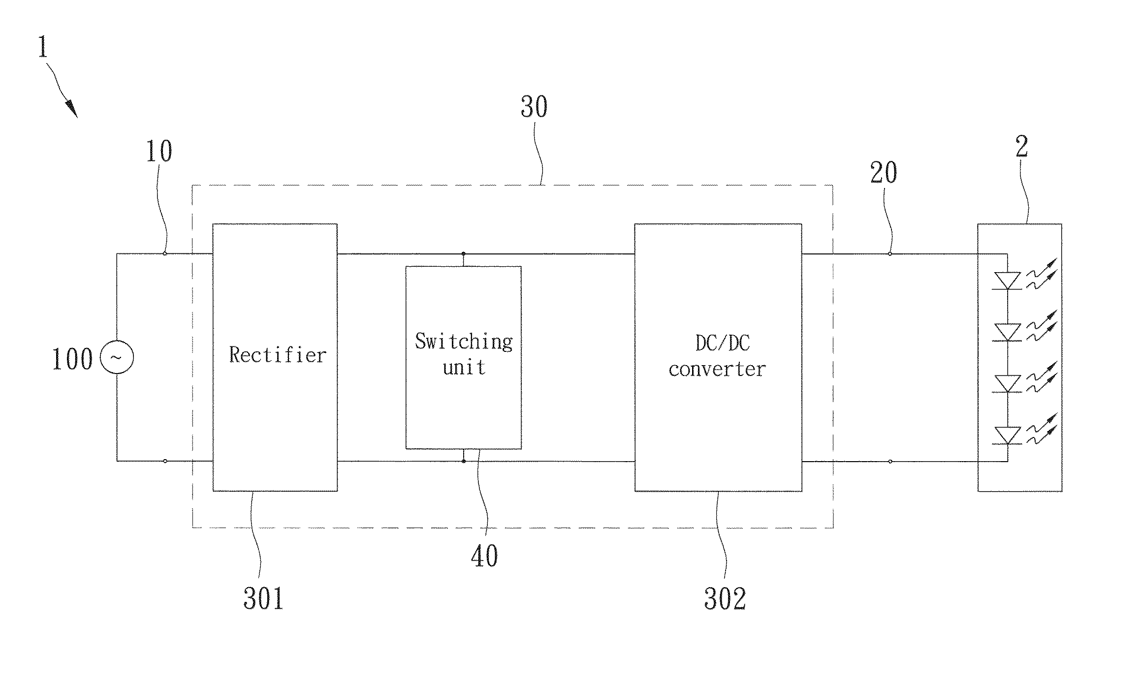
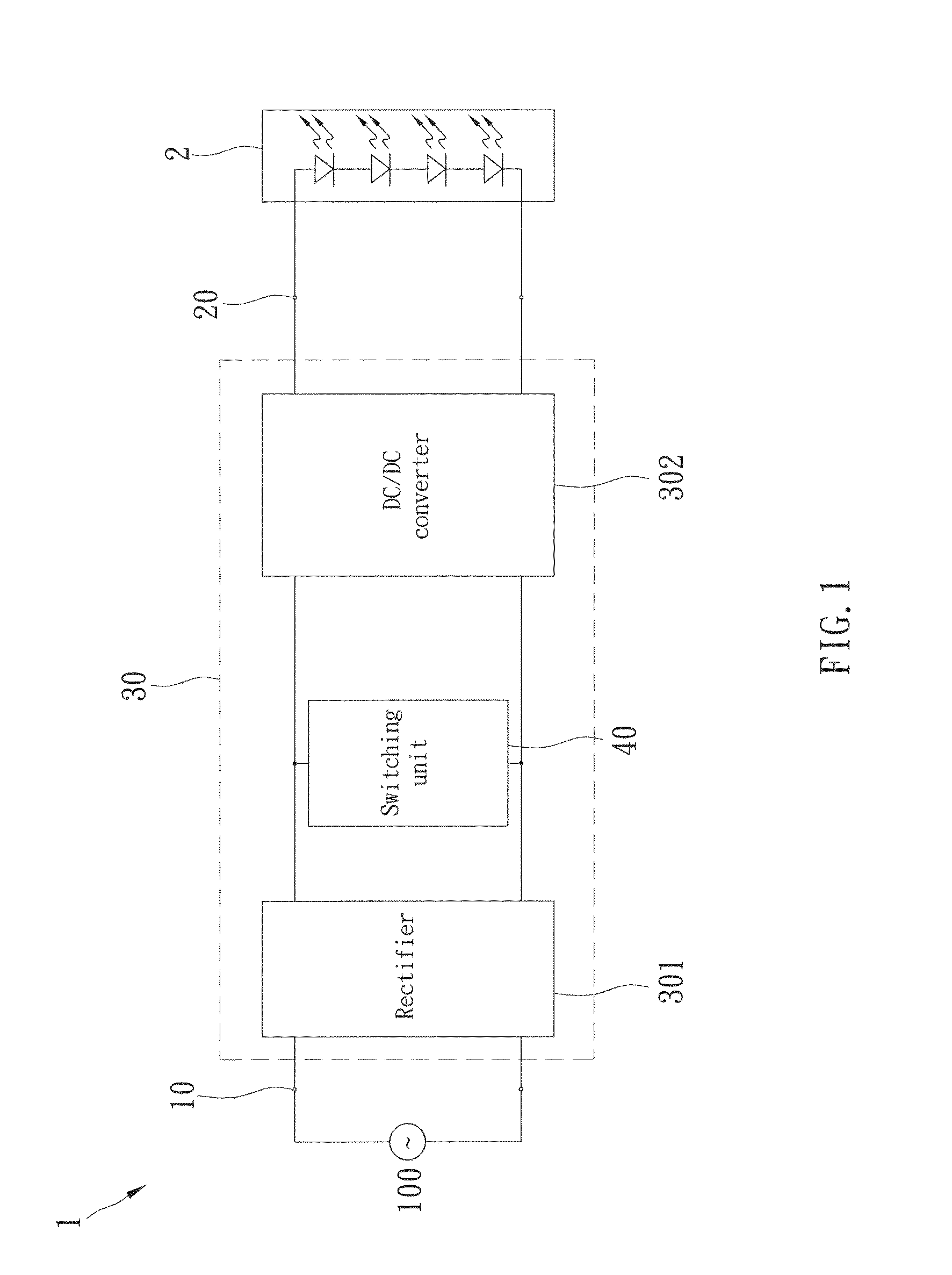
[0027]FIG. 1 shows a light source module of the first preferred embodiment, including a switching power supply 1 and plurality of LEDs 2. The switching power supply 1 receives power from an external power source 100, and supplies it to the LEDs 2. In the present invention, the power source 100 is AC power from the power station or AC / DC power from other power systems, such as wind power, solar power, geothermal power etc. The switching power supply 1 includes an input port 10, an output port 20, a transforming unit 30, and a switching unit 40.

[0028]The input port 10 electrically connects to the power source 100.

[0029]The output port 20 electrically connects to the LEDs 2.

[0030]The transforming unit 30 respectively connects to the input port 10 and the output port 20, and includes a rectifier 301 and a DC / DC converter 302. The rectifier 301 connects to the input port 10 to receive the AC current from the power source 100 and transform it into DC current. The DC / DC converter 302 conne...


PUM


Abstract

The present invention provides a light source module, including at least a LED and a switching power supply. The switching power supply has an input port, an output port, a transforming unit, and a switching unit. An external power source is connected to the input port, the LED is electrically connected to the output port, and the transforming unit is between the input port and the output port to receive power of the external power source through the input port, transform the power, and send the power to the light emitting diode through the output port. The switching unit includes a ringing choke converter electrically connected to the transforming unit to make the transforming unit provide a constant current to the LED by turning on and turning off the power outputting from the transforming unit.

Description

BACKGROUND OF THE INVENTION[0001]1. Field of the Invention[0002]The present invention relates generally to an optical device, and more particularly to a light source module.[0003]2. Description of the Related Art[0004]With advancement in technology, light-emitting diode (LED) is more and more popular in the modern market. LED has many advantages, including small size, short response time, long life, low decrement, strong surface, anti-vibration, emitting full-color light (including invisible light), low power loss, low radiant heat, and easy to manufacture. Therefore, more and more light sources use LED to replace conventional light bubble or tube.[0005]The difference between the LED and other electronic devices is that LED is activated by current, not by voltage. Consequently, a LED light source module usually is provided with a constant current switching power supply for supplying LEDs stable and constant current.[0006]In the present market, the switching power supply usually is p...

Claims


Application Information

Patent Timeline
IPC IPC(8): H05B37/02H05B44/00
CPCH05B33/0854H05B33/0815H05B45/3725H05B45/18
Inventor HUNG, TA-SHENGCHIEN, LIEN-TA
Owner HEP TECH
Why Eureka
Try Eureka