Blowout Container

a blowout container and container body technology, applied in the field of valves, can solve the problems of bop failure, over-estimation of the pressure of the entire stack of most bops in use today, and over-estimation of the pressure of the bop in the container, so as to achieve the effect of cost-effective and needed safe guard

Inactive Publication Date: 2013-05-23
BAKER DWIGHT
View PDF4 Cites 28 Cited by
  • Summary
  • Abstract
  • Description
  • Claims
  • Application Information

AI Technical Summary

Benefits of technology

[0019]A blowout container system designed for the major control of flowing fluids and gases during oil and gas well blowouts. The blowout container would be installed below the present blowout preventer stacks, and remain there during all drilling completion and production cycles throughout the lifetime of the well. Atop the blowout container all wellheads and production equipment would be installed. In the event of mishaps of blowouts and/or oil and gas seepage coming from inside the primary casing. The blowout container when activated via an umbilical tie back line to the surface would activate the shear/destroy elements inside their spool all pipes i

Problems solved by technology

Most blowouts, however, occur during the tripping phase of drilling and as a result, other drilling tools such as drill collars and/or down hole tools are frequently within the section to be closed.
A second significant cause for failure of blowout preventers used today results from the fact that typically only the body of the BOP is tested at API recommended pressures.
Therefore, the BOPs in use today are significantly overrated for higher pressures.
The entire stack of most BOPs in use today is therefore typically overstated (and thus overrated) in the pressures they will contain.
Other deteriorating effects can cause BOP failure.
For example because of the abrasive and often times corrosive nature of drilling fluids and methods used in drilling today the BOP bodies do not retard those things from invading between the BOP body and blowout preventer parts installed.
The cost of doing

Method used


Image

  • Blowout Container
  • Blowout Container
  • Blowout Container

Examples


Embodiment Construction

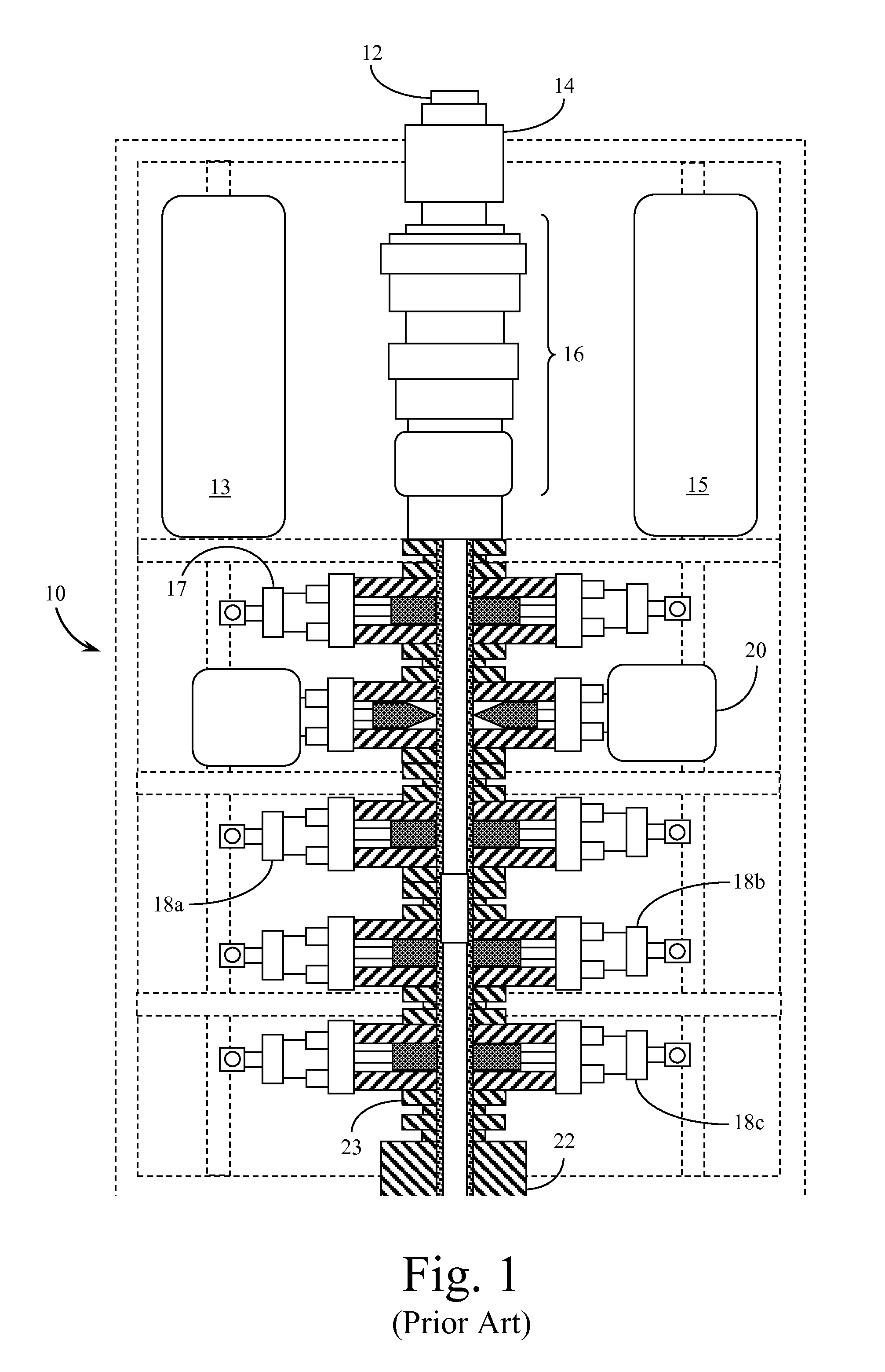
[0038]Reference is made first to FIG. 1 for a description of a typical blowout preventer of the prior art. In FIG. 1 blowout preventer (BOP) 10 is generally constructed in a stack comprising a series of valves developed to prevent an uncontrolled flow if the mud control system is overwhelmed. Extending downward through the stack, the system connects to the surface through riser adaptive 12 connecting to flex joint 14. Below this connection point are typically at least two annular valves designed to close in and seal on the drill pipe. If the drill pipe is not in use, these annular valves close in and shut off the open hole. Various control components are associated with the operation of these elements within the BOP system in control pods 13&15.

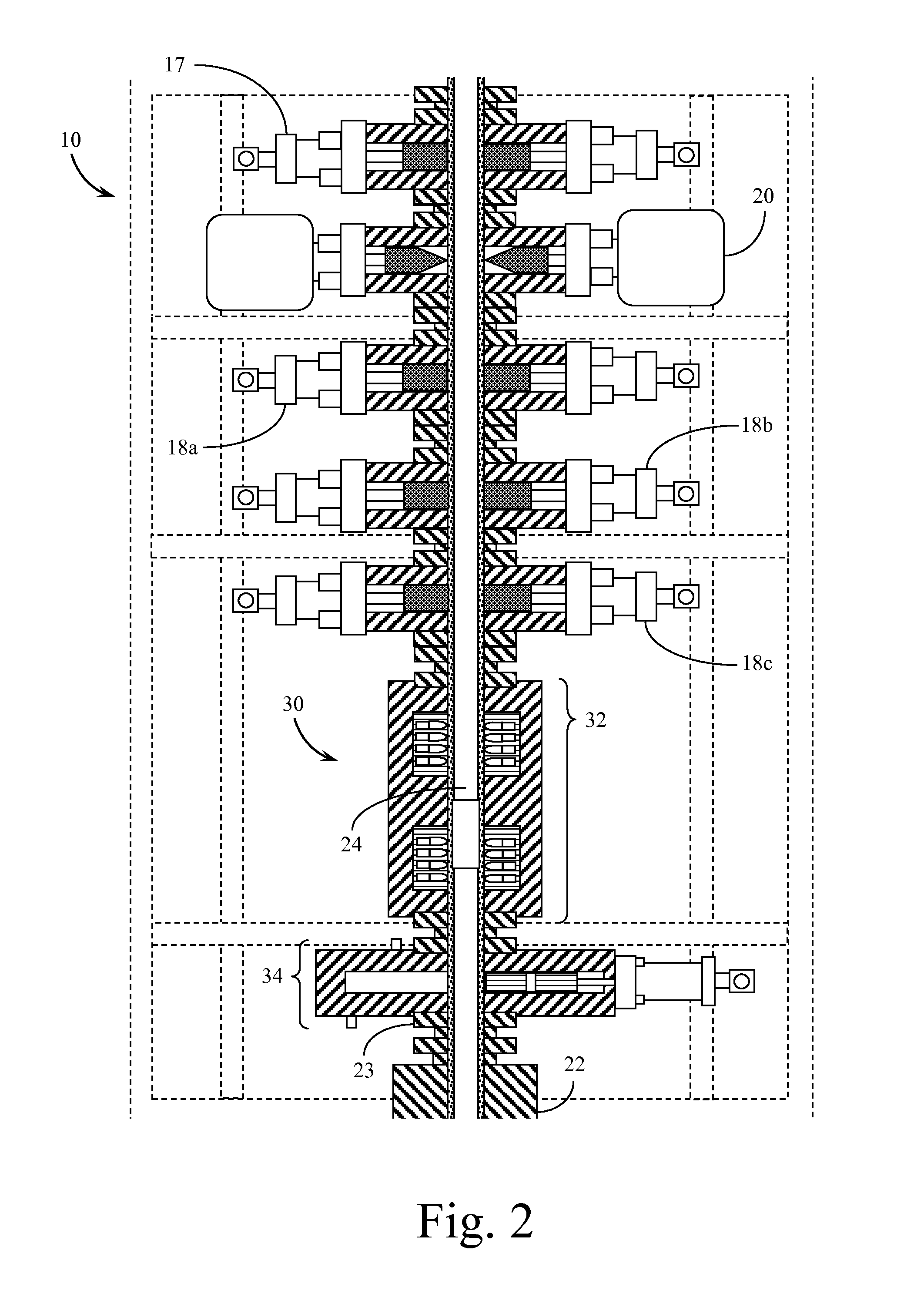
[0039]Below the annular valves 16 are configured a number of ram structures. These include a pipe ram 17, three (for example) blind rams 18a-18c as well as a shear ram 20. Blind rams can withstand more pressure than the annular valves over op...


PUM


Abstract

A system for containing and recovering from the blowout of an oil or gas well. The blowout containment (BOC) system is operable in place of, or as a failsafe alternative to, standard blowout preventer (BOP) systems. The BOC system includes a hydraulically operated gate valve positioned over the well at the wellhead. The gate valve includes a check valve operable when the gate valve is closed. The BOC system further includes at least one shearing assembly positioned over the gate valve. The shearing assembly orients explosive charges into the well flow path. An activation trigger detonates the explosive charges to clear the well flow path of obstructions to permit the gate valve to close. Operation of the BOC system is preferably monitored and controlled from a remote location apart from the rig associated with the well.

Description

CROSS REFERENCES TO RELATED APPLICATIONS[0001]This application claims the benefit under Title 35 United States Code §119(e) of U.S. Provisional Application 61 / 517,453, filed Apr. 20, 2011, the full disclosure of which is incorporated herein by reference.BACKGROUND OF THE INVENTION[0002]1. Field of the Invention[0003]The present invention relates generally to valves, and more particularly, but not by way of limitation, to an improved gate valve for controlling the flow of fluids from a well during wild well blowouts. The present invention relates further to devices for shearing / severing any and all drilling tools inside a drilling blowout preventer (BOP), or likewise all the pipe or tubing inside the largest casing size during the production phase for land and subsea service. The present invention therefore relates to an improved gate valve for controlling the flow of drilling fluids and hydrocarbon fluids and gases in a state of free flow known as blowout in drilling and production ...

Claims


Application Information

Patent Timeline
IPC IPC(8): E21B33/06
CPCE21B29/02E21B33/06E21B33/063
Inventor BAKER, DWIGHT
Owner BAKER DWIGHT
Why Eureka
Try Eureka