
Wireless light communication system and wireless light communication method using the same

a wireless light and communication system technology, applied in the direction of electromagnetic transmission, electrical equipment, close-range type systems, etc., can solve the problem that the system may not receive an accurate optical signal

Active Publication Date: 2013-05-30
SAMSUNG ELECTRONICS CO LTD
View PDF16 Cites 61 Cited by
  • Summary
  • Abstract
  • Description
  • Claims
  • Application Information

AI Technical Summary

Benefits of technology

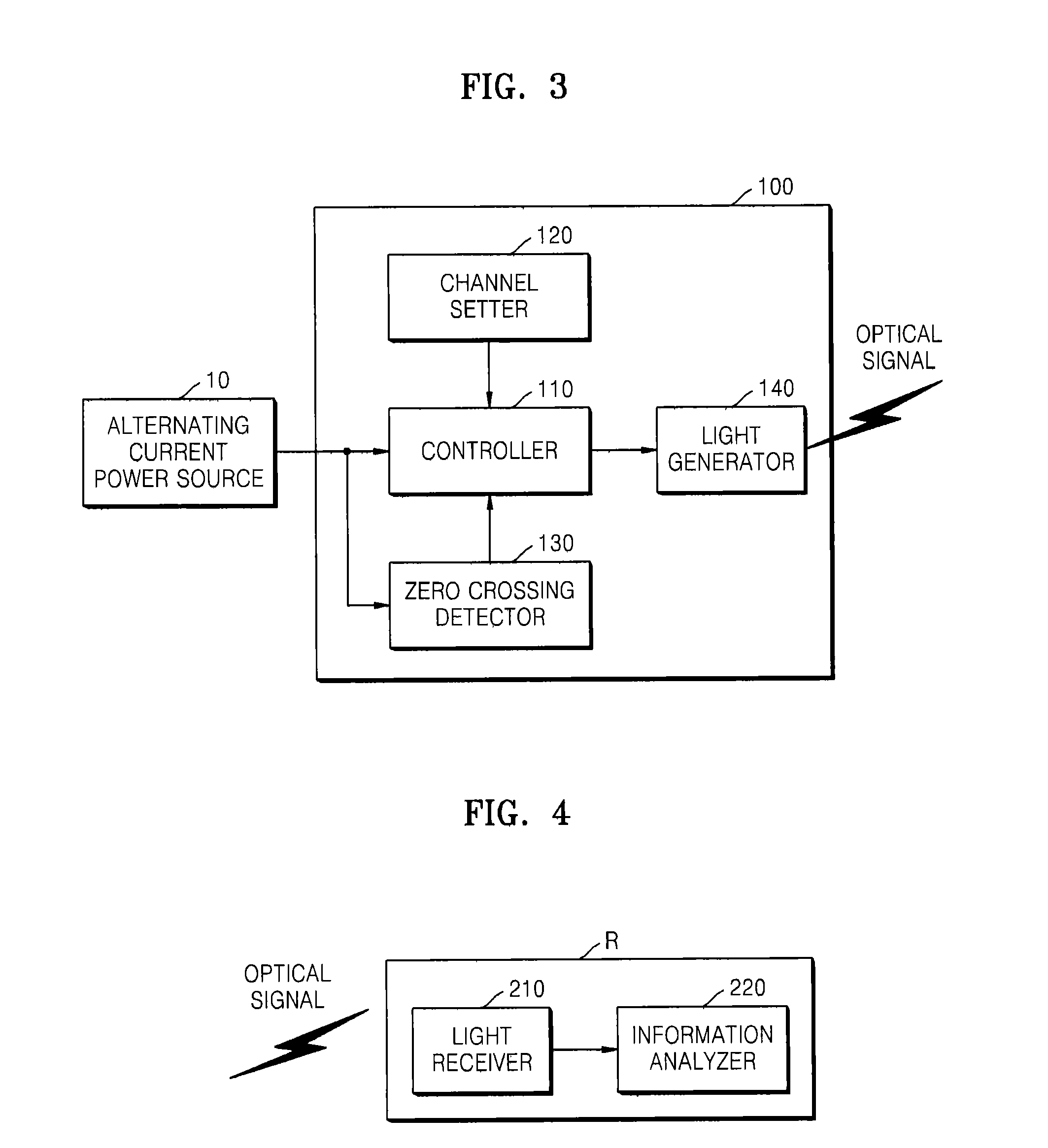
The present invention provides a wireless communication system and method that can prevent interference when multiple optical signals are received. The system detects the zero crossing of the AC power and generates a channel synchronous signal based on the detected zero crossing. The system then sets a time slot for each channel and allows the light generator to transmit an optical signal during the set time slot. This helps to ensure that optical signals from different light transmitting units do not interfere with each other. The technical effect of this invention is to provide a more reliable and efficient wireless communication system with reduced interference.

Problems solved by technology

In this case, the optical signals may interfere with each other, and thus the system may not receive an accurate optical signal.

Method used


Image

  • Wireless light communication system and wireless light communication method using the same
  • Wireless light communication system and wireless light communication method using the same
  • Wireless light communication system and wireless light communication method using the same

Examples


Embodiment Construction

[0033]Exemplary embodiments are described in greater detail with reference to the accompanying drawings.

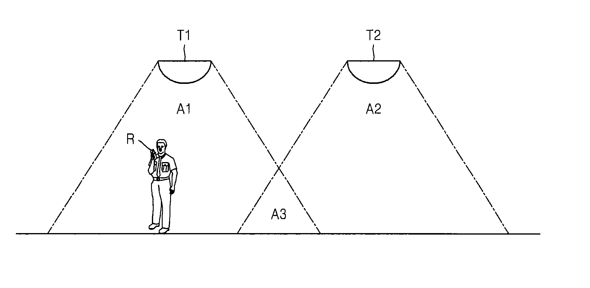
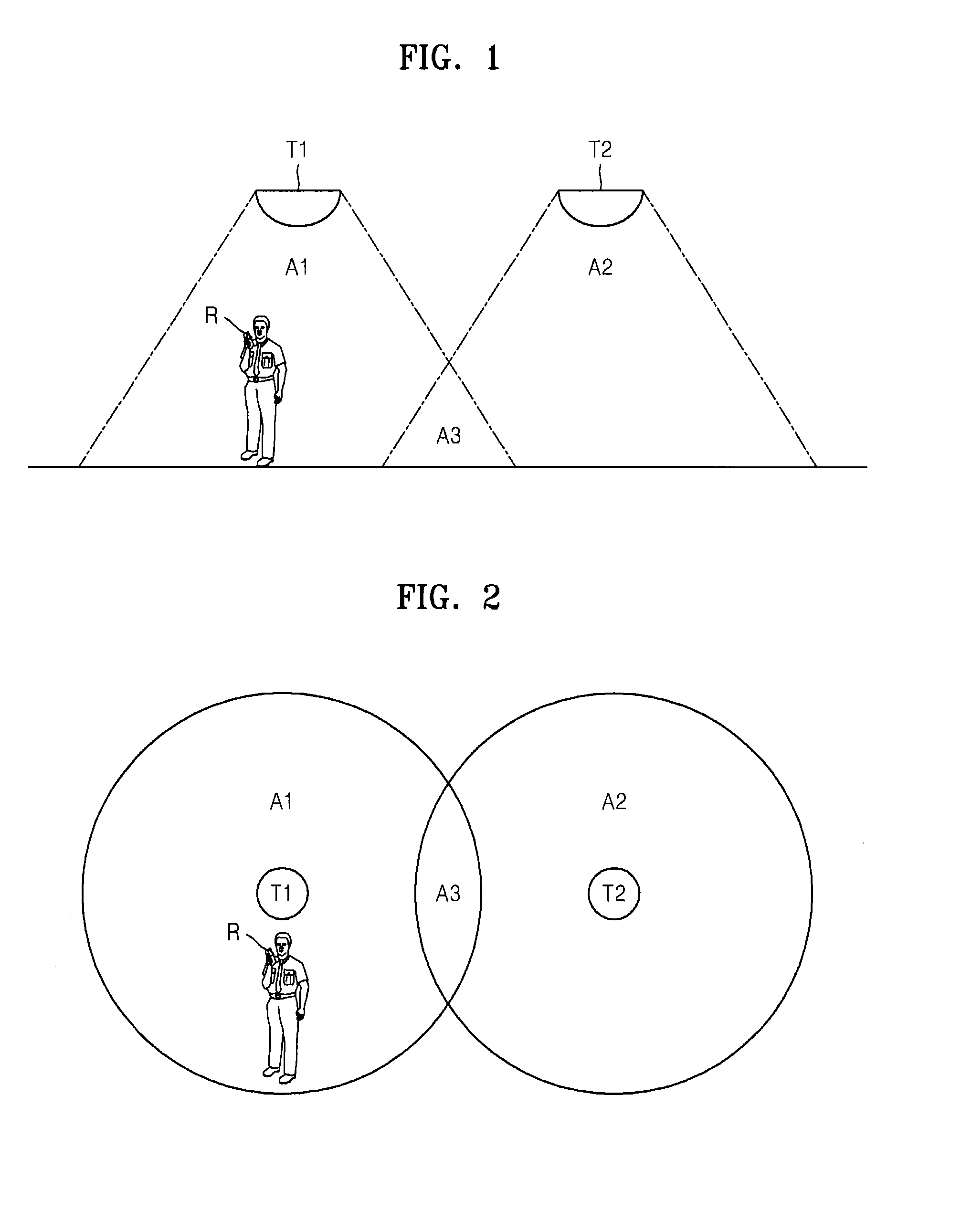
[0034]FIG. 1 illustrates a wireless light communication system according to an exemplary embodiment of the present invention, and FIG. 2 illustrates a wireless light communication system of FIG. 1. The wireless light communication system of FIGS. 1 and 2 may use light emitting diode (LED) lighting as light transmitting units T1 and T2, wherein the light transmitting units T1 and T2 transmit optical signals including their own location information via dimming control. According to an exemplary embodiment, information included in an optical signal may be location information, but alternatively, other types of information may be included in the optical signal. According to an exemplary embodiment, the light transmitting units T1 and T2 may be LED lighting, but alternatively, a light transmitting unit or the like that generates an infrared light may be used. An exemplary method of gen...


PUM


Abstract

A wireless light communication system and method using a plurality of light transmitting units driven by a same alternating current (AC) power, and a light receiving unit for receiving optical signals transmitted by the plurality of light transmitting units are provided. The wireless light communication method includes setting a channel for each of the plurality of light transmitting units such that light transmitting units having an overlapping area that is reachable by optical signals use different channels, detecting zero crossing of the AC power, synchronizing channels by using the detected zero crossing, and transmitting an optical signal through the set channel by using the plurality of light transmitting units, and receiving the optical signal transmitted by each of the plurality of light transmitting units by using the light receiving unit, and analyzing information included in the received optical signal.

Description

CROSS-REFERENCE TO RELATED APPLICATIONS[0001]This application is related to and claims priority to Korean Patent Application No. 10-2011-0127221, filed on Nov. 30, 2011, in the Korean Intellectual Property Office, the disclosure of which is incorporated herein.BACKGROUND[0002]1. Field[0003]The embodiments discussed herein relate to a wireless light communication system and a wireless light communication method.[0004]2. Description of the Related Art[0005]A wireless light communication method for exchanging information by wirelessly transmitting and receiving an optical signal including the information is widely used. An example of the wireless light communication method is an infrared communication method using an infrared light. Due to light emitting diode (LED) lighting being used widely, a wireless light communication method of controlling dimming of the LED lighting is of great interest.[0006]A wireless light communication method may be used in a system for determining location ...

Claims


Application Information

Patent Timeline
Patent Type & Authority Applications(United States)
IPC IPC(8): H04B10/10
CPCH04B10/116H04B10/11
Inventor PARK, SEONG-MANCHOI, YOUNG-JUN
Owner SAMSUNG ELECTRONICS CO LTD
Learn More