
User Interface For Artifact Removal In An EEG

a user interface and artifact technology, applied in the field of analyzing an eeg recording, can solve the problems of one of the most difficult problems, lack of techniques,

Active Publication Date: 2013-05-30
PERSYST DEV
View PDF10 Cites 24 Cited by
  • Summary
  • Abstract
  • Description
  • Claims
  • Application Information

AI Technical Summary

Benefits of technology

The present invention provides a user interface for removing artifacts from EEG data. This is useful for two main reasons: first, it ensures that the cleaner EEG correctly represents what would be present in the absence of artifact, and second, it allows the user to see the original signal or a partially cleaned version to determine if there is useful information present. Additionally, the invention allows for stitching together the results of artifact removal from different epochs, using a weighted average based on the distance between the epoch centers. This stitching can be done using various methods.

Problems solved by technology

However, these techniques are still lacking.
Learning what is an artifact and how to see what is in the underlying signal is one of the most difficult problems in EEG interpretation.

Method used


Image

  • User Interface For Artifact Removal In An EEG
  • User Interface For Artifact Removal In An EEG
  • User Interface For Artifact Removal In An EEG

Examples


Embodiment Construction

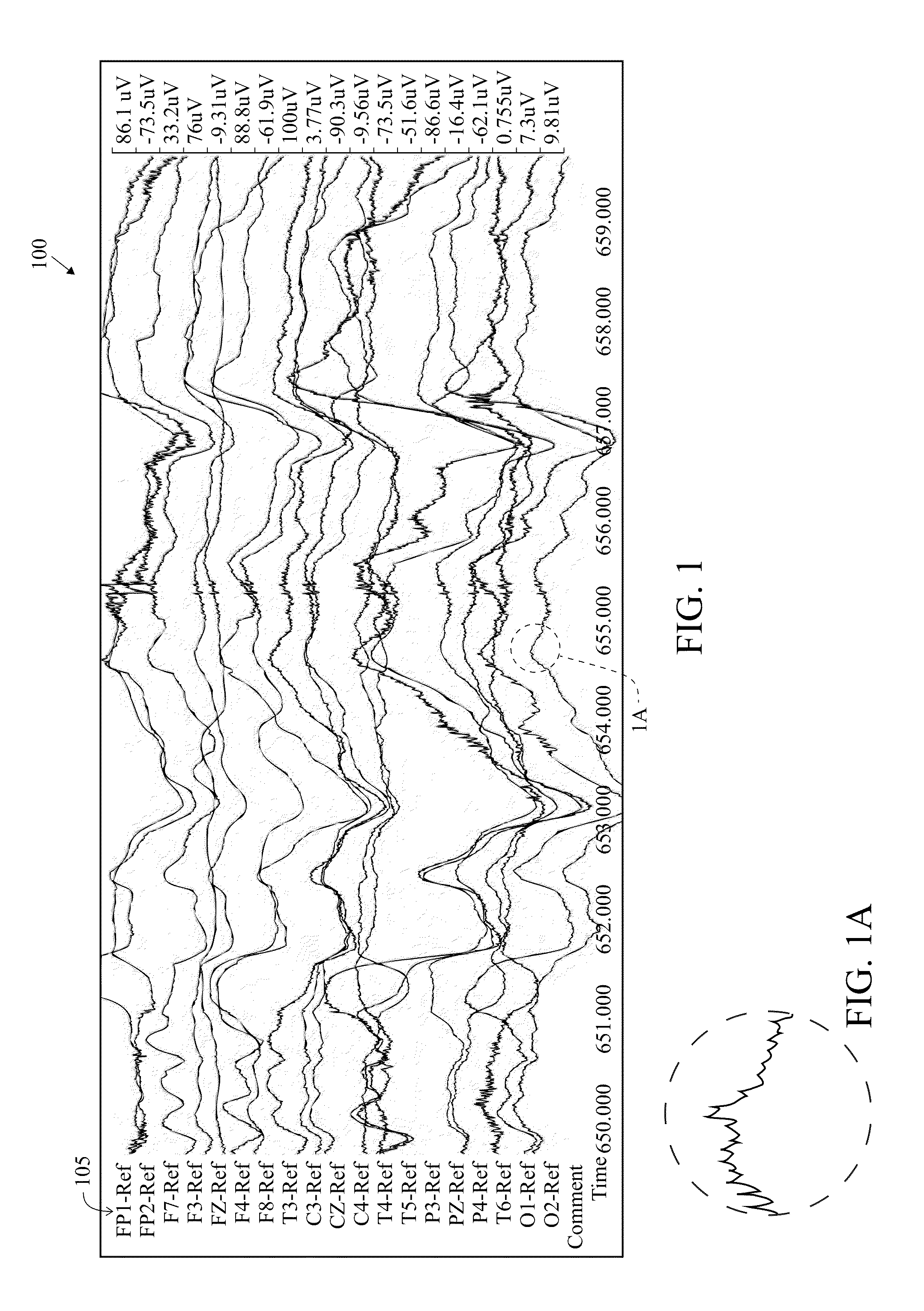
[0107]A raw or original EEG report 100 is shown in FIG. 1. The original EEG report 100 has a plurality of channels FP1-Ref through to O2-Ref, shown at the Y axis 105 of the report. The X-axis of the report is time. The original EEG report 100 has not been subjected to artifact reduction. The original EEG report contains artifacts from various sources such as muscle movement, eye movement, sweating, electrode cables and the like. However, the EEG may also have certain activity that a physician or technician is looking for from the EEG report in order to accurately analyze the patient's brain activity. For example, the activity shown in FIG. 1A at a time 655.000 may represent a certain stage of brain activity for the patient that is important to the physician or technician. However, normally, the physician or technician will not review the raw EEG report 100 due to the presence of artifacts.

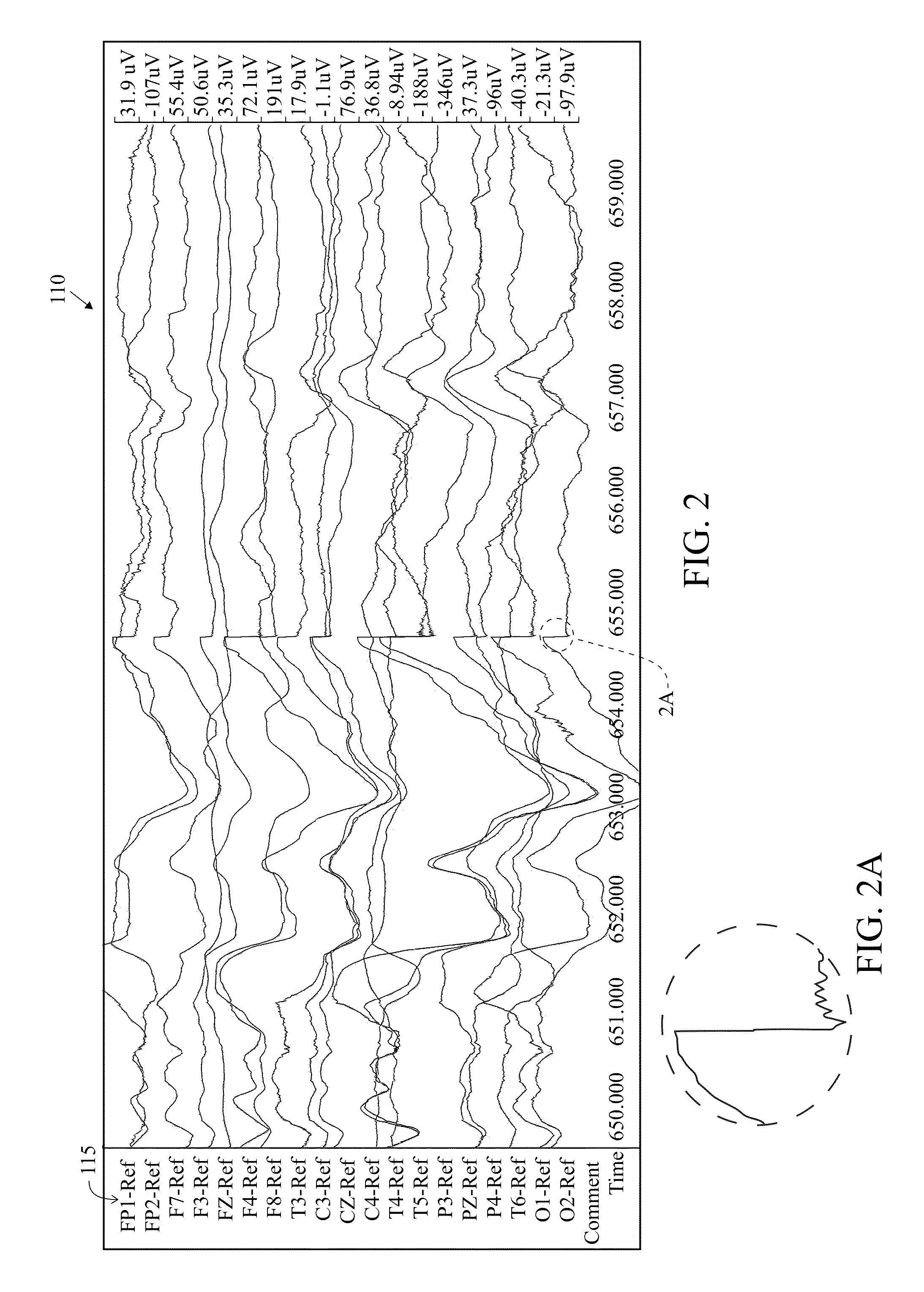
[0108]FIG. 2 is an illustration of a processed EEG report 110 of the original EEG report 100 of...


PUM


Abstract

A method and system for a user interface for artifact removal in an EEG is disclosed herein. The invention allows an operator to select a plurality of artifacts to be automatically removed from an EEG recording using a user interface. The operator pushes a button on the user interface to apply a plurality of filters to remove the plurality of artifacts from the EEG and generate a clean EEG for viewing.

Description

CROSS REFERENCES TO RELATED APPLICATIONS[0001]The Present application claims priority to U.S. Provisional Patent Application No. 61 / 563,839, filed on Nov. 28, 2011, the Present application is a continuation-in-part application of U.S. patent application Ser. No. 13 / 620,784, filed on Sep. 15, 2012, which claims priority to U.S. Provisional Patent Application No. 61 / 563,731, filed on Nov. 25, 2011, and the Present application is also a continuation-in-part application of U.S. patent application Ser. No. 13 / 542,665, filed on Jul. 6, 2012, all of which are hereby incorporated by reference in their entireties.STATEMENT REGARDING FEDERALLY SPONSORED RESEARCH OR DEVELOPMENT[0002]Not ApplicableBACKGROUND OF THE INVENTION[0003]1. Field of the Invention[0004]The present invention generally relates to a method and system for displaying EEG data. More specifically, the present invention relates to analyzing an EEG recording.[0005]2. Description of the Related Art[0006]An electroencephalogram (“...

Claims


Application Information

Patent Timeline
IPC IPC(8): A61B5/04A61B5/00A61B5/0476
CPCA61B5/04017A61B5/0476A61B5/7203G06F19/3406A61B5/7207A61B5/7246A61B5/725A61B5/742A61B5/316A61B5/369G16H40/63A61B5/7425A61B5/743A61B5/7475A61B5/291
Inventor NIERENBERG, NICOLASWILSON, SCOTT B.SCHEUER, MARK L.
Owner PERSYST DEV
Learn More