Electrosurgical Instrument with a Knife Blade Lockout Mechanism

Active Publication Date: 2013-05-30
TYCO HEALTHCARE GRP LP
View PDF13 Cites 78 Cited by
  • Summary
  • Abstract
  • Description
  • Claims
  • Application Information

AI Technical Summary

Benefits of technology

[0017]In certain instances, the knife blade lockout mechanism may be positioned proximal to the first and second jaw members and the first and second jaw members may be pivotably coupled to one another via a first pivot pin extending through the shaft. In this particular instance, a second pivot pin extending through the knife blade lockout mechanism is positioned within a pair of slots defined through the drive tube such that the knife blade lockout mechanism pivots about the second p

Problems solved by technology

Under certain surgical scenarios, however, such as, for example, when the lever is in a “latched” configuration (i.e., the knife blade is operable to sever tissue) and a thick bundle of tissue is positioned between the jaw members, there exists a possibility of the knife blade deploying and wandering or drifting out of the knife slot(s) on the jaw member(s) and becoming tr

Method used


Image

  • Electrosurgical Instrument with a Knife Blade Lockout Mechanism
  • Electrosurgical Instrument with a Knife Blade Lockout Mechanism
  • Electrosurgical Instrument with a Knife Blade Lockout Mechanism

Examples


Embodiment Construction

[0036]Detailed embodiments of the present disclosure are disclosed herein; however, the disclosed embodiments are merely examples of the disclosure, which may be embodied in various forms. Therefore, specific structural and functional details disclosed herein are not to be interpreted as limiting, but merely as a basis for the claims and as a representative basis for teaching one skilled in the art to variously employ the present disclosure in virtually any appropriately detailed structure.

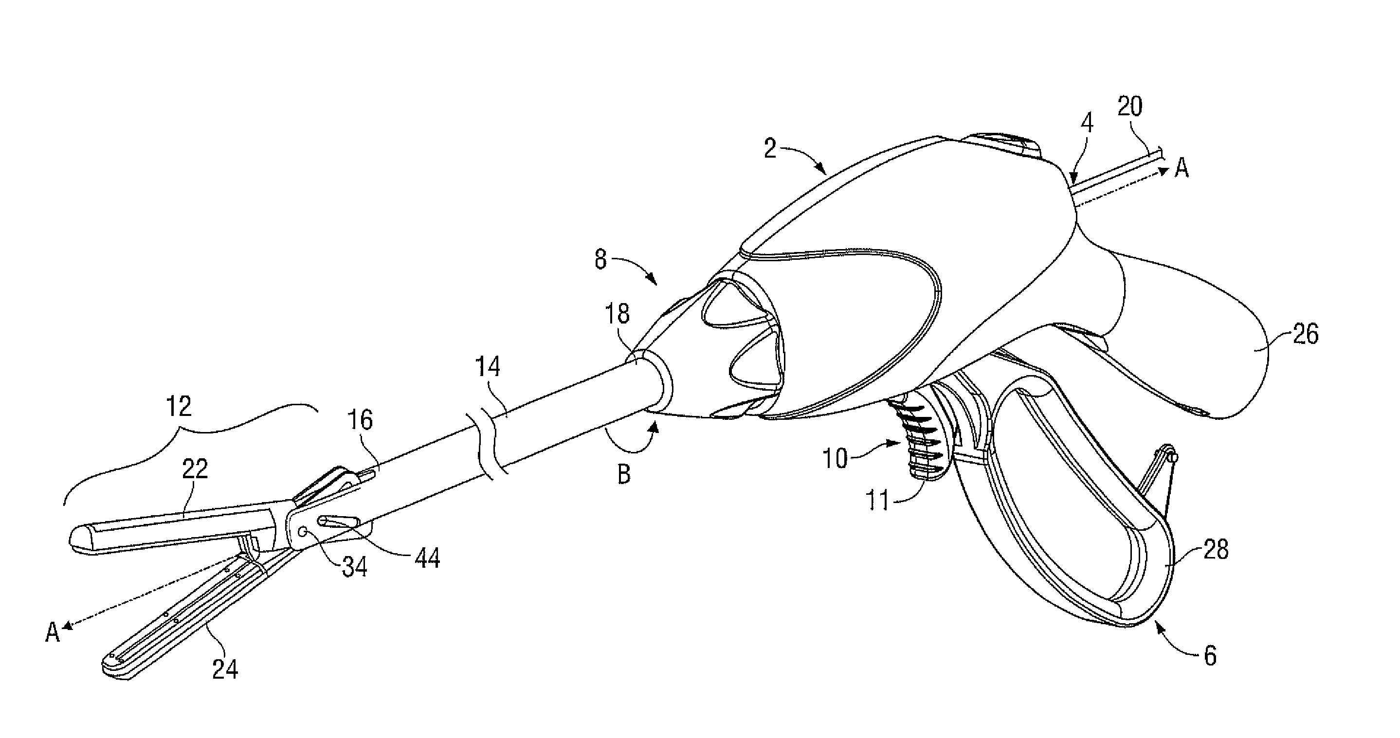
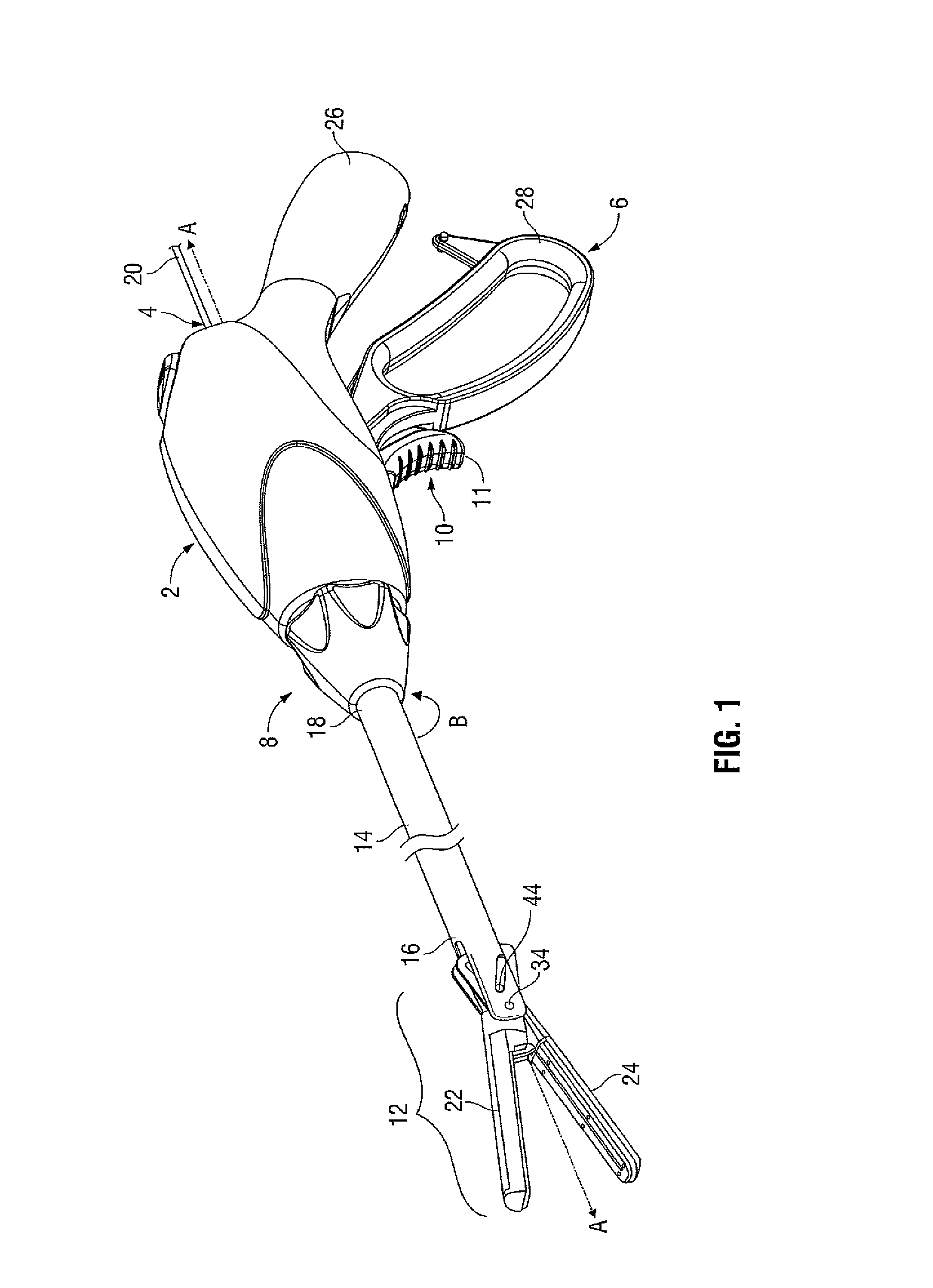
[0037]Turning now to FIG. 1, an electrosurgical endoscopic forceps 2 configured for use with a knife blade lockout mechanism 40 (mechanism 40, see FIG. 3) is illustrated. Forceps 2 is provided having a longitudinal axis “A-A” defined therethrough, a housing 4, a handle assembly 6, a rotating assembly 8, a trigger assembly 10 and an end effector assembly 12. Forceps 2 further includes a shaft 14 having a distal end 16 configured to mechanically engage end effector assembly 12 and a proximal end 18 ...


PUM


Abstract

An electrosurgical forceps is provided with a shaft that extends from a housing of the electrosurgical forceps. An end effector assembly operably coupled to the shaft includes a pair of first and second jaw members. One or both of the first and second jaw members is movable from an open configuration, to a clamping configuration. A knife blade assembly includes a knife blade translatable within the first and second jaw members. A knife blade lockout mechanism is in operative communication with the knife blade assembly and includes an elongated cam slot with a cam pin translatable therein from a distal end of the elongated cam slot corresponding to the knife blade lockout mechanism engaged with the knife blade assembly, to a proximal position corresponding to the knife blade lockout mechanism disengaged from the knife blade assembly.

Description

BACKGROUND[0001]1. Technical Field[0002]The present disclosure relates to an electrosurgical instrument and, more particularly, to an electrosurgical instrument including jaw members and a knife blade lockout mechanism that is configured to prevent unintentional deployment of a knife blade when the jaw members are in a spaced-apart configuration.[0003]2. Description of Related Art[0004]Electrosurgical forceps are well known in the medical arts. For example, an electrosurgical endoscopic forceps is utilized in surgical procedures, e.g., laparoscopic surgical procedure, where access to tissue is accomplished through a cannula or other suitable device positioned in an opening on a patient. The endoscopic forceps, typically, includes a housing; a handle assembly including a movable handle; a drive assembly; a shaft; a cutting mechanism such as, for example, a knife blade assembly; and an end effector assembly attached to a distal end of the shaft. The end effector includes jaw members t...

Claims


Application Information

Patent Timeline
IPC IPC(8): A61B18/12A61B17/285
CPCA61B2019/481A61B18/085A61B18/1445A61N2007/025A61B2018/00607A61B2018/00994A61B2018/1455A61B18/1447A61B2090/08021A61B17/29A61B2017/2925A61B2017/2946A61B2017/2947A61N7/02
Inventor TWOMEY, JOHN R.CHOJIN, EDWARD M.
Owner TYCO HEALTHCARE GRP LP
Why Eureka
Try Eureka