Transmission and transmission housing with multiple dipsticks and dipstick apertures, circumferentially positioned internal lugs and an adjacent fluid inlet port

a transmission and dipstick technology, applied in the direction of gearing control, gear lubrication/cooling, gearing elements, etc., can solve the problems of catastrophic transmission failure, dipstick vulnerable to damage, and inability to easily remove the oil pan

Active Publication Date: 2013-06-06
REID DENNIS
View PDF9 Cites 11 Cited by
  • Summary
  • Abstract
  • Description
  • Claims
  • Application Information

AI Technical Summary

Benefits of technology

[0004]In such transmissions, an oil pan is mounted and sealed to a bottom of the housing, and provides a reservoir for automatic transmission fluid used to operate the transmission. An oil pump, which is typically positioned toward a front of the transmission housing, is in fluid communication

Problems solved by technology

This leaves the dipstick vulnerable to damage as the bottom of the vehicle is exposed and unprotected to road debris.
The dipstick and or guide tube can easily snag road debris and become dislodged or ripped from the access port, which then drains the transmission fluid from the oil pan, potentially causing catastrophic failure of the transmission.
When the guide tube is attached to the oil pan, the oil pan cannot be easily removed because the dipstick and/or the guide tube hangs up or attaches to parts or areas in the engine compartment.
This makes servicing more difficult and time consuming.
Accordingly, access to the dipstick may be compromised and difficult to reach.
However, if lugs were formed in the gap, the lugs would block the protrusion on the plug forming the pocket and the plug could not be removed.
It is known that, at least with respect to the use of this transmission housing in competitive vehicles as described above, the existence of the gap compromises the structural integrity of the transmission housing.
A snap ring is disposed within a slot aligned in each of the lugs, and moving transmission components bump or push against the support ring causing mechanical stress on the lugs.
As the end lugs at the gap are exposed to additional stresses, they tend to crack or break fir

Method used


Image

  • Transmission and transmission housing with multiple dipsticks and dipstick apertures, circumferentially positioned internal lugs and an adjacent fluid inlet port
  • Transmission and transmission housing with multiple dipsticks and dipstick apertures, circumferentially positioned internal lugs and an adjacent fluid inlet port
  • Transmission and transmission housing with multiple dipsticks and dipstick apertures, circumferentially positioned internal lugs and an adjacent fluid inlet port

Examples


Embodiment Construction

[0030]Reference will now be made in detail to the embodiments consistent with the invention, examples of which are illustrated in the accompanying drawings. Wherever possible, the same reference numerals are used throughout the drawings and refer to the same or like parts.

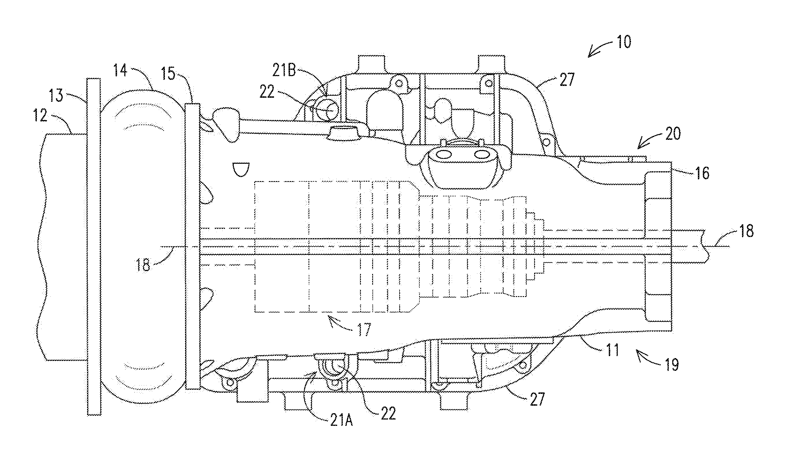
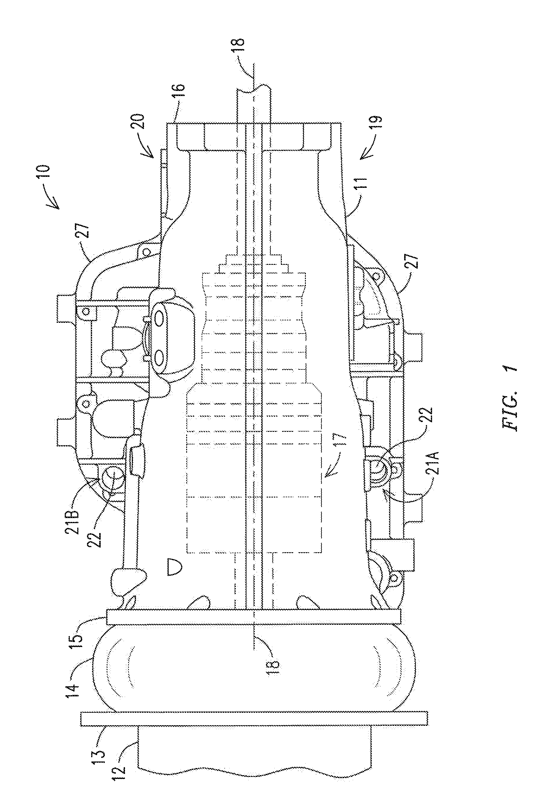
[0031]With respect to FIG. 1, a transmission 10 is shown including a transmission housing 11 with its front end 15 connected to an engine 12 via a torque converter 14 and flexplate 13. The transmission 10 includes the housing 11 and transmission components 17 (schematically shown), such as gears, clutches, shafts, valve bodies, etc., which are encased within the housing 10 and transmit rotary power generated by the engine 12 to an output shaft and an axle (not shown).

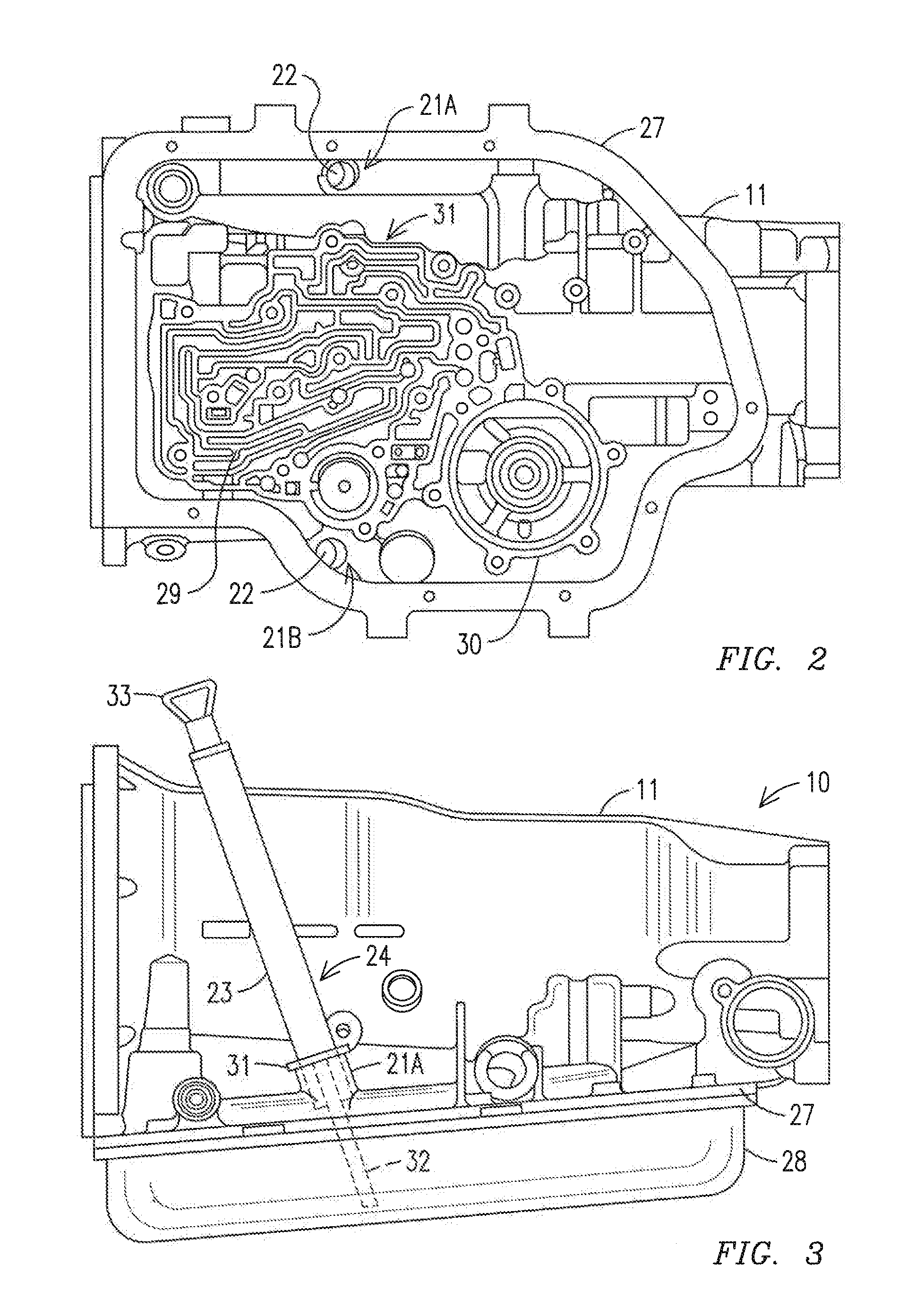
[0032]As shown in FIG. 3, an oil pan 28 is mounted to a bottom of the transmission housing 11. More specifically, the housing 11 includes a flange 27 at a bottom of the housing 11; and, the oil pan 28 includes a matching flange that is bolted to the fl...


PUM


Abstract

A transmission housing, or transmission including a transmission housing, having a plurality of oil pan access ports positioned on the housing for receiving in each access port, or one of the access ports, a transmission fluid indicator that is used to monitor a level of transmission fluid in an oil pan mounted to a bottom of the transmission housing. The transmission fluid indicator may be a manual indicator, such as a dipstick, or an automated indicator, such as a sensor that is configured to generate one or more electrical signals indicative of a level of the transmission fluid in the oil pan.

Description

CROSS-REFERENCE TO RELATED APPLICATIONS[0001]This is a Continuation-In-Part of U.S. application Ser. No. 13 / 411,723 filed Mar. 5, 2012, which claims the benefit of U.S. Provisional Application No. 61 / 567,211 filed Dec. 6, 2011, and incorporated herein by reference in its entirety.BACKGROUND OF THE INVENTION[0002]This invention generally relates to transmissions for marine and land vehicles and machines and more particularly to transmission housings used to house the components of transmissions. More specifically, the invention pertains to transmission fluid dipsticks used in connection with a transmission to determine levels of transmission fluid available for operation of the transmission. Another aspect of the invention relates to internal lugs that are circumferentially spaced on an internal surface of the transmission housing for securing in place components of a transmission. In addition, the invention pertains to injection additional cooled transmission fluid into the transmis...

Claims


Application Information

Patent Timeline
IPC IPC(8): F16H57/02
CPCF16H57/0452F16H57/02Y10T74/2186F16H57/0494F16H57/0447
Inventor REID, DENNIS
Owner REID DENNIS
Why Eureka
Try Eureka