Bidirectional Downhole Fluid Flow Control System and Method

a fluid flow control and bidirectional technology, applied in the direction of fluid removal, borehole/well accessories, sealing/packing, etc., can solve the problems of inability to achieve the desired injection flow rate and pressure profile by reverse flow through conventional flow control devices, and inability to achieve the desired injection flow rate and pressure profile. , to achieve the effect of greater resistance to flow, and greater resistance to flow

Active Publication Date: 2013-06-06
HALLIBURTON ENERGY SERVICES INC
View PDF3 Cites 32 Cited by
  • Summary
  • Abstract
  • Description
  • Claims
  • Application Information

AI Technical Summary

Benefits of technology

[0008]In one embodiment, the at least one injection flow control component may be a fluidic diode providing greater resistance to flow in the production direction than in the injection direction. In this embodiment, the fluidic diode may be a vortex diode wherein injection fluid flow entering the vortex diode travels primarily in a radial direction and wherein production fluid flow entering the vortex diode travels primarily in a tangential direction. In another embodiment, the at least one production flow control component may be a fluidic diode providing greater resistance to flow in the injection direction than in the production direction. In this embodiment, the fluidic diode may be a vortex diode wherein production fluid flow entering the vortex diode travels primarily in a radial direction and wherein injection fluid flow entering the vortex diode travels primarily in a tangential direction.
[0009]In one embodiment, the at least one injection flow control component may be a fluidic diode providing greater resistance to flow in the production direction than in the injection direction in series with a nozzle having a throat portion and a diffuser portion operable to enable critical flow therethrough. In other embodiments, the at least one injection flow control component may be a fluidic diode providing greater resistance to flow in the production direction than in the injection direction in series with a fluid selector valve. In certain embodiments, the at least one production flow control component may be a fluidic diode providing greater resistance to flow in the injection direction than in the production direction in series with an inflow control device.
[0010]In another aspect, the present invention is directed to a bidirectional downhole fluid flow control system. The system includes at least one injection vortex diode and at least one production vortex diode. In this configuration, injection fluid flow entering the injection vortex diode travels primarily in a radial direction while production fluid flow entering the injection vortex diode travels primarily in a tangential direction. Likewise, production fluid flow entering the production vortex diode travels primarily in a radial direction while injection fluid flow entering the production vortex diode travels primarily in a tangential direction.
[0011]In one embodiment, the at least one injection vortex diode may be in series with a nozzle having a throat portion and a diffuser portion operable to enable critical flow therethrough. In another embodiment, the at least one injection vortex diode may be in series with a fluid selector valve. In a further embodiment, the at least one production vortex diode may be in series with an inflow control device. In certain embodiments, the at least one injection vortex diode may be a plurality of injection vortex diodes in parallel with each other. In other embodiments, the at least one production vortex diode may be a plurality of production vortex diodes in parallel with each other.
[0012]In a further aspect, the present invention is directed to a bidirectional downhole fluid flow control method. The method includes providing a fluid flow control system at a target location downhole, the fluid flow control system having at least one injection flow control component and at least one production flow control component in parallel with the at least one injection flow control component; pumping an injection fluid from the surface into a formation through the fluid flow control system such that the injection fluid experiencing greater flow resistance through the production flow control component than through the injection flow control component; and producing a formation fluid to the surface through the fluid flow control system such that the production fluid experiencing greater flow resistance through the injection flow control component than through the production flow control component. The method may also include pumping the injection fluid through parallel opposing fluid diodes, each having direction dependent flow resistance, producing the formation fluid through parallel opposing fluid diodes, each having direction dependent flow resistance, pumping the injection fluid through parallel opposing vortex diodes, each having direction dependent flow resistance, producing the formation fluid through parallel opposing vortex diodes, each having direction dependent flow resistance or pumping the injection fluid through an injection fluid diode having direction dependent flow resistance and a nozzle in series with the fluid diode, the nozzle having a throat portion and a diffuser portion operable to enable critical flow therethrough.
[0013]In an additional aspect, the present invention is directed to a bidirectional downhole fluid flow control system. The system includes at least one injection flow control component and at least one production flow control component, in parallel with the at least one injection flow control component. The at least one injection flow control component has direction dependent flow resistance such that inflow of production fluid experiences a greater flow resistance through the at least one injection flow control component than outflow of injection fluid through the at least one injection flow control component.

Problems solved by technology

In wells having multiple zones, due to differences in the pressure and / or permeability of the zones as well as pressure and thermal losses in the tubular string, the amount of steam entering each zone may be difficult to control.
It has been found, however, that achieving the desired injection flowrate and pressure profile by reverse flow through conventional flow control devices is impracticable.
As the flow control components are designed for production flowrates, attempting to reverse flow through conventional flow control components at injection flowrates causes an unacceptable pressure drop.

Method used


Image

  • Bidirectional Downhole Fluid Flow Control System and Method
  • Bidirectional Downhole Fluid Flow Control System and Method
  • Bidirectional Downhole Fluid Flow Control System and Method

Examples


Embodiment Construction

[0025]While the making and using of various embodiments of the present invention are discussed in detail below, it should be appreciated that the present invention provides many applicable inventive concepts which can be embodied in a wide variety of specific contexts. The specific embodiments discussed herein are merely illustrative of specific ways to make and use the invention, and do not delimit the scope of the present invention.

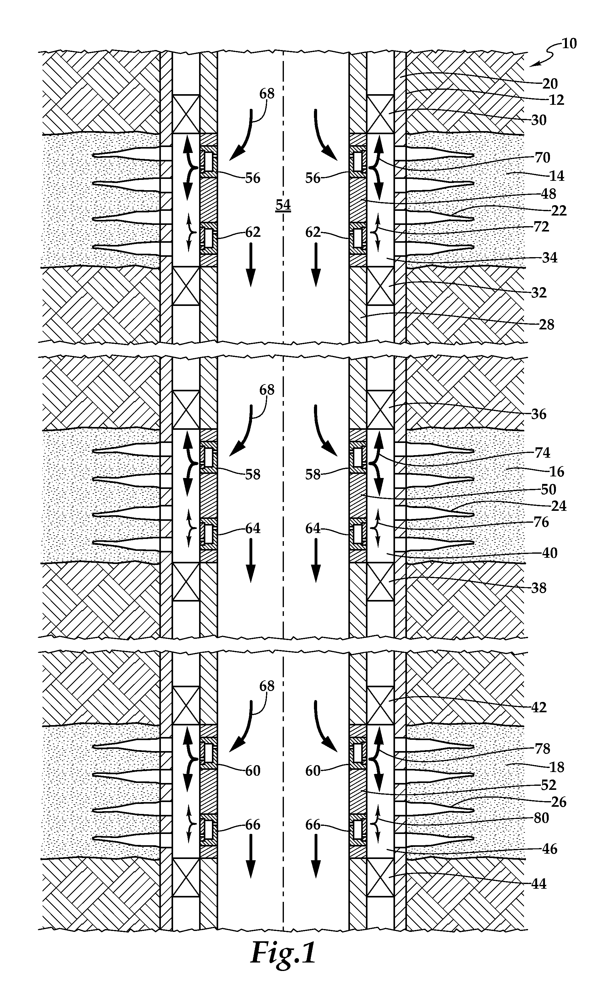
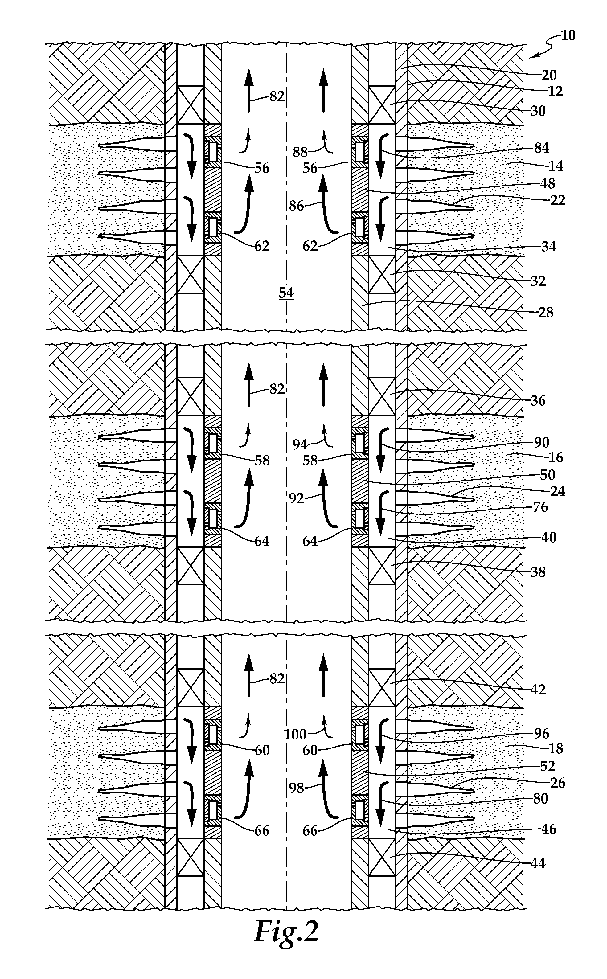
[0026]Referring initially to FIG. 1, a well system including a plurality of bidirectional downhole fluid flow control systems positioned in a downhole tubular string is schematically illustrated and generally designated 10. A wellbore 12 extends through the various earth strata including formations 14, 16, 18. Wellbore 12 includes casing 20 that may be cemented within wellbore 12. Casing 20 is perforated at each zone of interest corresponding to formations 14, 16, 18 at perforations 22, 24, 26. Disposed with casing 20 and forming a generally annular are...


PUM


Abstract

A bidirectional downhole fluid flow control system is operable to control the inflow of formation fluids and the outflow of injection fluids. The system includes at least one injection flow control component and at least one production flow control component in parallel with the at least one injection flow control component. The at least one injection flow control component and the at least one production flow control component each have direction dependent flow resistance, such that injection fluid flow experiences a greater flow resistance through the at least one production flow control component than through the at least one injection flow control component and such that production fluid flow experiences a greater flow resistance through the at least one injection flow control component than through the at least one production flow control component.

Description

CROSS-REFERENCE TO RELATED APPLICATIONS[0001]This application claims the benefit under 35 U.S.C. §119 of the filing date of International Application No. PCT / US2011 / 063582, filed Dec. 6, 2011. The entire disclosure of this prior application is incorporated herein by this reference.TECHNICAL FIELD OF THE INVENTION[0002]This invention relates, in general, to equipment utilized in conjunction with operations performed in subterranean wells and, in particular, to a downhole fluid flow control system and method that are operable to control the inflow of formation fluids and the outflow of injection fluids.BACKGROUND OF THE INVENTION[0003]Without limiting the scope of the present invention, its background will be described with reference to steam injection into a hydrocarbon bearing subterranean formation, as an example. During the production of heavy oil, oil with high viscosity and high specific gravity, it is sometimes desirable to inject a recovery enhancement fluid into the reservoir...

Claims


Application Information

Patent Timeline
Patent Type & Authority Applications(United States)
IPC IPC(8): E21B34/08E21B34/06
CPCE21B43/12E21B34/08E21B43/16
Inventor FRIPP, MICHAEL LINLEYDYKSTRA, JASON D.DEJESUS, ORLANDO
Owner HALLIBURTON ENERGY SERVICES INC
Why Eureka
Try Eureka