Stand

a technology of stand and stand, which is applied in the field of stand, can solve the problems of not working for the stand of the indicated, needing correction, and requiring a certain skill in dealing with such surgical stands

Inactive Publication Date: 2013-06-06
LEICA MICROSYSTEMS (SCHWEIZ) AG
View PDF3 Cites 24 Cited by
  • Summary
  • Abstract
  • Description
  • Claims
  • Application Information

AI Technical Summary

Benefits of technology

[0009]Disadvantageously, however, they require a certain skill in dealing with such surgical stands. Leaving that aside, stands of this kind constructed on the double-beam principle are extremely expensive.
[0010]Examples of such known constructions are found in U.S. Pat. No. 5,528,417 A and EP 628290 A1; these also indicate the manner in which microscope mounts held by parallelogram carrier arms of double-beam stands are to be held in a perpendicular position even upon pivoting of the parallelogram carrier arm. This occurs by way of a lever-like brace (crank member) on a vertical stand carrier arm, which is connected on the one hand via a tie rod to the microscope holder, and on the other hand to a non-pivotable stationary part of the surgical stand. This construction has already been disclosed previously in the art in the context of a wide variety of designs, for example in the design of light sources held in the manner of a beam balance for desk lamps, or the like.
[0011]If the surgeon does not possess the necessary skill or experience, however, and if the magnification set on the surgical microscope is perhaps also very high, then despite lever-like bracing, simply positioning the surgical microscope (in some cases only a little bit) higher causes the specimen or the surgical field to quickly escape away of the center of the observation field or entirely out of it. This can result in disorientation, and can require repositioning of the surgical microscope. This, however, leads to a loss of time during the procedure, which is not only undesirable but can also in fact be inherently disadvantageous in terms of the procedure.
[0012]The object of the present invention is thus to create a novel stand that avoids the problems indicated above, preferably without resorting to the double-beam principle and thus in economical fashion.
[0013]The novel stand is intended essentially to exhibit only slight technical modifications, however, so that a majority of the components used hitherto can be reused (including parts of stands according to the double-beam principle).
[0014]The stand is intended in particular to allow the surgeon to perform elevation adjustments on the surgical microscope without thereby necessarily displacing the main axis in space or with reference to a perpendicular.

Problems solved by technology

At greater magnifications, this can result in a need for correction.
This does not work for the stand of the indicated existing art as shown, since the stand is standing on the floor and does not permit the desired degree of freedom.
Disadvantageously, however, they require a certain skill in dealing with such surgical stands.
Leaving that aside, stands of this kind constructed on the double-beam principle are extremely expensive.
If the surgeon does not possess the necessary skill or experience, however, and if the magnification set on the surgical microscope is perhaps also very high, then despite lever-like bracing, simply positioning the surgical microscope (in some cases only a little bit) higher causes the specimen or the surgical field to quickly escape away of the center of the observation field or entirely out of it.
This can result in disorientation, and can require repositioning of the surgical microscope.
This, however, leads to a loss of time during the procedure, which is not only undesirable but can also in fact be inherently disadvantageous in terms of the procedure.

Method used


Image

  • Stand
  • Stand
  • Stand

Examples


Embodiment Construction

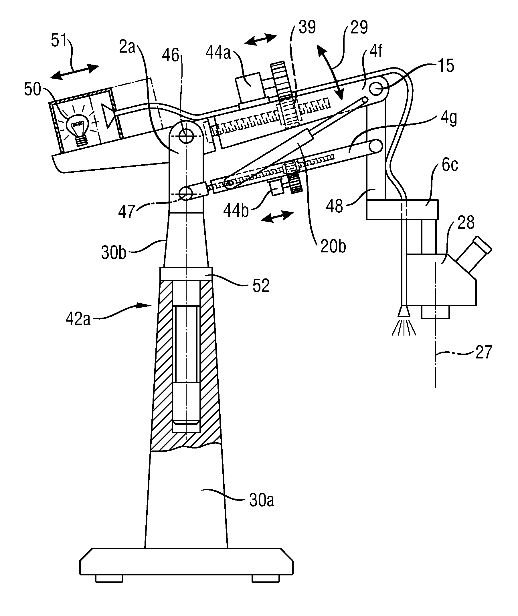
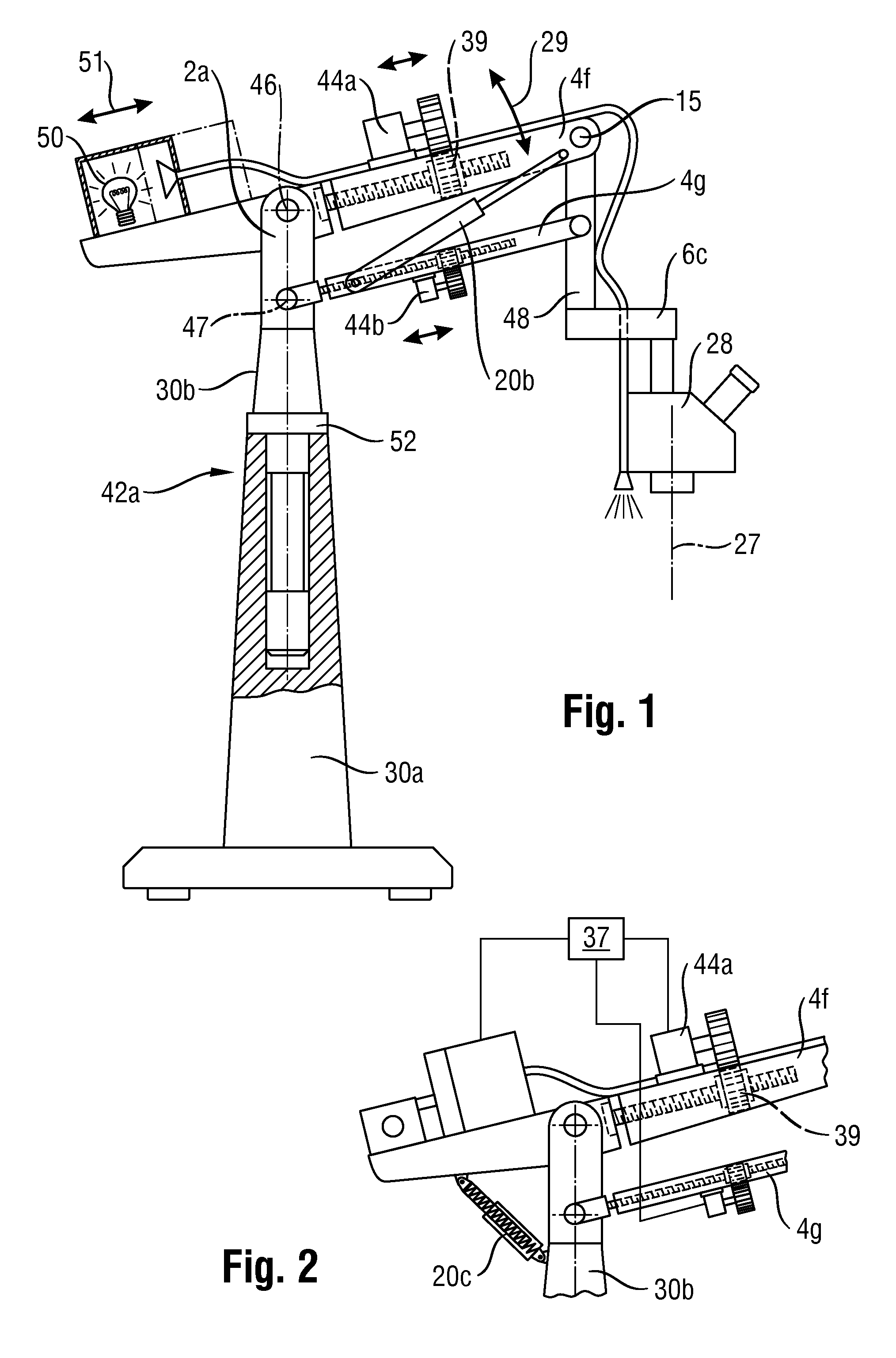
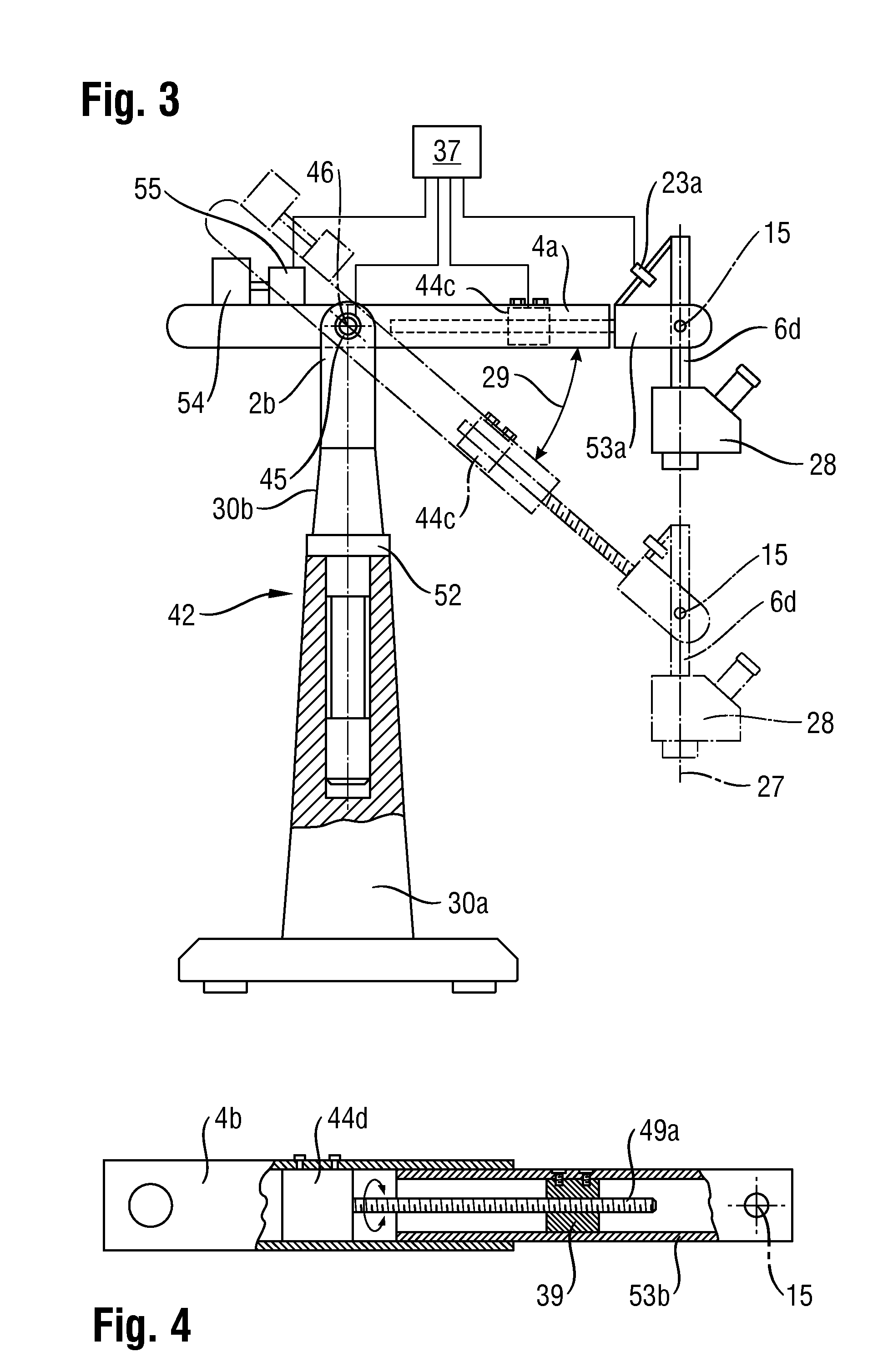
[0065]FIG. 1 shows a conventional stand according to DE 10042272 A1, but having an elongation capability according to the present invention of the carrier arm or of the parts of carrier arm 4f, 4g that are assembled with their proximal and distal ends into a parallelogram carrier arm. The two parts of carrier arm 4f and 4g thus form the upper and the lower tier of a two-tier carrier arm. Each of the partial carrier arms 4f and 4g is embodied to be extendable (preferably simultaneously and to the same distance), so that the distance between the distal end and the proximal rotation axes 46 and 47, respectively, of said partial carrier arms 4f, 4g can be increased or decreased. These length modifications are usually carried out synchronously and over the same length, but special embodiments in which the two partial carrier arms can be extended to different lengths, so as thereby to effect arbitrary positioning of a microscope holder 6c that is articulatedly connected via a carrier part...


PUM


Abstract

The invention relates to a stand for a surgical microscope (28) having a pivotable carrier arm (4). The latter is modifiable in length as a function of its pivot angle (29). It carries a microscope holder (6), pivotable in at least one plane, at the distal end of carrier arm (4), the angular position (21; 24) of the microscope holder (6) being definable with reference to the carrier arm (4; 34) according to a further development; and a motorized drive, which engages on the one hand on the carrier arm and on the other hand on the microscope holder (6), and in the context of operation defines the angular position (21; 24) in remotely controlled fashion and/or automatically.

Description

CROSS REFERENCE TO RELATED APPLICATIONS[0001]This application claims priority of German patent application number 10 2011 119 813.3 filed Dec. 1, 2011, the disclosure of which is incorporated by reference in its entirety.[0002]This application is also related to concurrently filed, co-pending, and commonly assigned application entitled “Stand,” bearing U.S. Ser. No. ______ and having internal reference number 033997.00187, claiming priority to German patent application number 10 2011 119 814.1 filed Dec. 1, 2011, the disclosures of which are hereby incorporated by reference in their entirety.FIELD OF THE INVENTION[0003]The invention relates to a stand, in particular to a stand for a surgical microscope.BACKGROUND OF THE INVENTION[0004]During the procedure surgical microscopes are as a rule positioned above a patient, or the surgical area to be observed is located on the patient and the surgeon looks down from above, along the main axis, onto the surgical area. The surgical microscop...

Claims


Application Information

Patent Timeline
Patent Type & Authority Applications(United States)
IPC IPC(8): F16M11/00
CPCF16M11/00F16M11/18F16M11/2064A61B2019/266F16M2200/044A61B19/26A61B2019/265F16M11/2092A61B2090/506A61B90/25A61B90/50A61B2090/508F16M2200/063
Inventor FRICK, ROMANSANDER, ULRICHSCHUTZ, MARCO
Owner LEICA MICROSYSTEMS (SCHWEIZ) AG
Why Eureka
Try Eureka