
Eureka
For R&D, Eureka makes reading and utilizing patents & technical documents easy.
Eureka AIR
Designed for self-driven R&D workflows. Generate viable solutions, solve complex R&D challenges, empower your innovation with AI.

Eureka Materials
Designed for material experts only. Revolutionize your material R&D, from search, analyze, to developing new materials.

TechResearch
Generate reliable direction feasibility study reports for your R&D in just a few steps.

TechSeek
Discover and master advanced knowledge NOW. Basics, ideas, possibilities, all at once.

TechMind
As an expert in R&D Theories, TechMind can generates customized viable solutions instantly.

TechRisk
Analyze your overall solution with one click, know your potential R&D risks in advance.

TechMonitor
Get weekly tech updates, stay abreast of the latest tech innovations and key insights.
Solar mirror panels and their manufacture
- Summary
- Abstract
- Description
- Claims
- Application Information
AI Technical Summary
Benefits of technology
Problems solved by technology
Method used
Image

Examples
Embodiment Construction
[0083]Panel
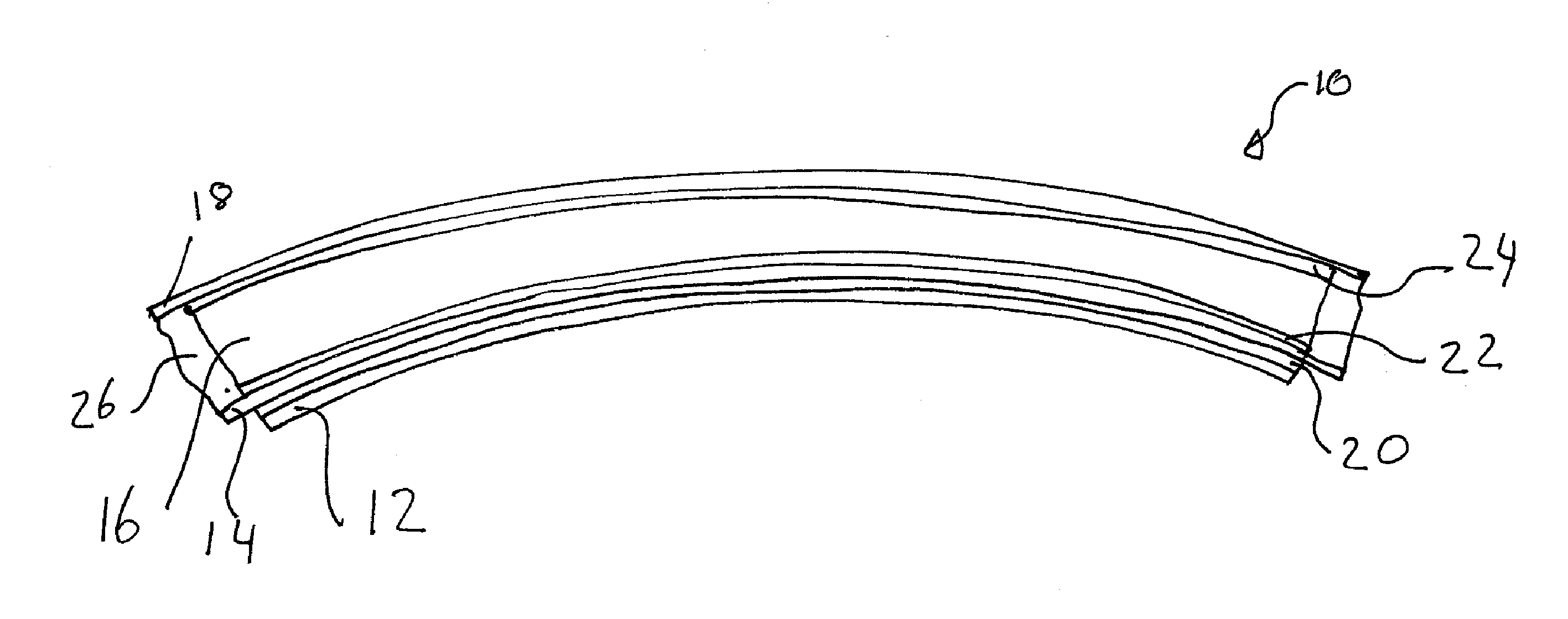
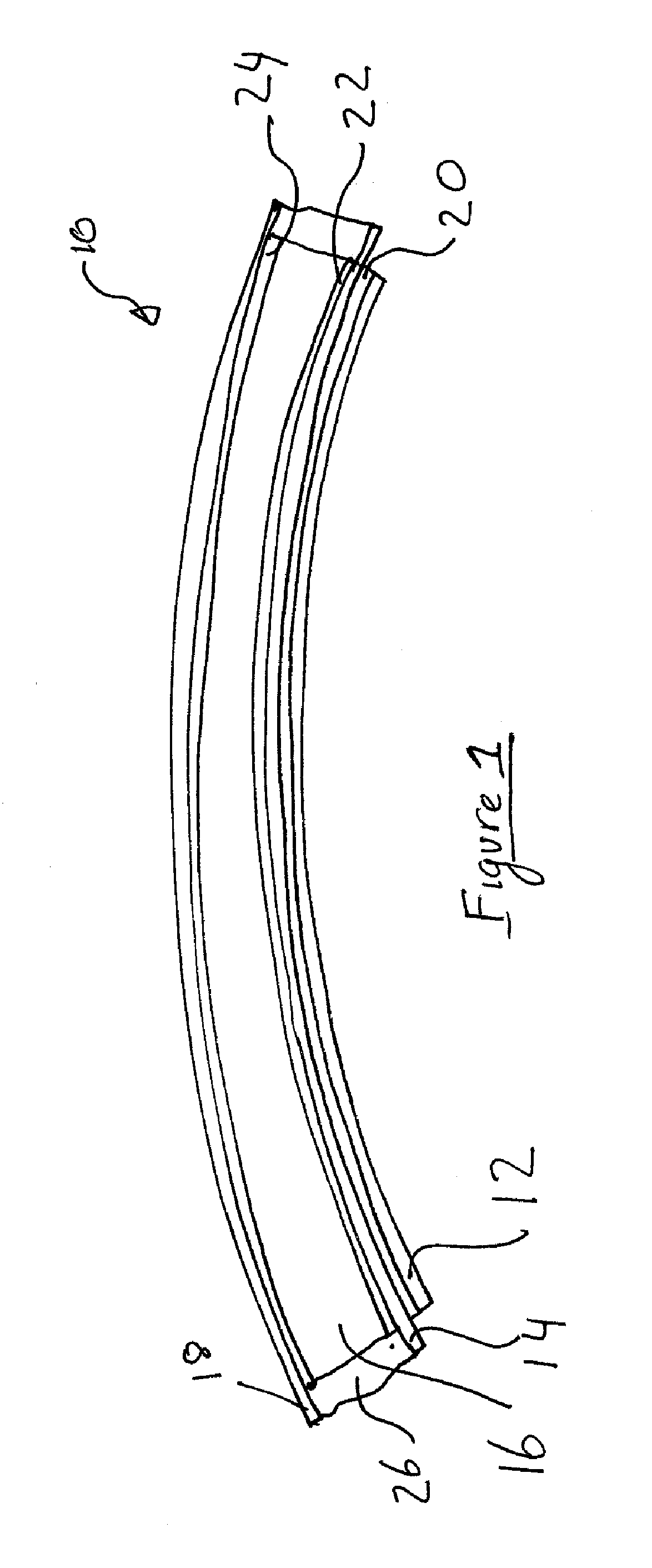
[0084]Referring to the drawings there is shown a solar mirror panel 10. The panel is comprised of a reflective member 12, two stiffening members, 14, 18 and a spacer member 16. The spacer member 16 is sandwiched between the two stiffening members 14, 18 and one of the stiffening members 14 is sandwiched between the spacer member 16 and the reflective member 12. Three layers of adhesive 20, 22 and 24, preferably hot melt adhesive, are located between adjacent members and secure the members together. The setting temperature(s) of the hot melt adhesive layers 20, 22 and 24 is above the anticipated temperatures the panel may be exposed to during transport, manufacture and use. A setting temperature of greater than about 75 centigrade is preferred.
[0085]The spacer member 16 serves to separate the two stiffening members and increase the stiffness of the panel compared to a panel having the same amount of stiffening material in a single layer.
[0086]The two stiffening members 14,...
PUM
 Abstract
Description
Claims
Application Information
 - R&D Engineer
- R&D Manager
- IP Professional
- Industry Leading Data Capabilities
- Powerful AI technology
- Patent DNA Extraction
Browse by: Latest US Patents, China's latest patents, Technical Efficacy Thesaurus, Application Domain, Technology Topic, Popular Technical Reports.
© 2024 PatSnap. All rights reserved.Legal|Privacy policy|Modern Slavery Act Transparency Statement|Sitemap|About US| Contact US: help@patsnap.com