LED Street Lamp Base

a technology for street lamps and lampshades, applied in the field of street lamps, can solve the problem that the lighting angle cannot be adjusted to fit other street lamps

Inactive Publication Date: 2013-06-13
SENGLED OPTOELECTRONICS
View PDF5 Cites 31 Cited by
  • Summary
  • Abstract
  • Description
  • Claims
  • Application Information

AI Technical Summary

Benefits of technology

[0004]The invention provides a LED street lamp base that can adjust lighting angle according to street situation against the existing shortage.
[0012]As a preference, the up and down ends on periphery of clamp ring are set with sliding plates parallel to each other on which raised slide block is set; the internal side of left side plate is set with cavity to hold clamp ring while up and down ends of it are respectively set with 1 slide rail in which the slide block mentioned is set. Two parallel sliding plates are in touch with up and down ends of cavity to prevent clamp ring from circumferential turning, and slide block is set in slide rail to prevent clamp ring dropping from cavity.
[0014]As a preference, the LED lighting module mentioned above consists of radiator unit and heat conduction subplate of which top surface is to connect with radiator unit and bottom surface is set with print circuit and several LEDs. Circular ring and bulb are respectively set on left and right end faces of radiator unit. LED lighting module is an overall modeling including several LEDs forming a lighting tube that features in easy maintenance and replacement as well as good light concentration effect.

Problems solved by technology

For the shortage of LED in optical performance, if you want to set LED light source on traditional lamp, it can only be done during the period of manufacture that is to carry out light distribution design according to the specific street lighting situation, namely to design lighting direction of each or each group of LED lamp, to light different street area and gain the overall lighting effect; the above mentioned street lamp can only be suitable for specific street lighting and each or each group of LED light towards fixed directions, so the lighting angle cannot be adjusted to fit for other street lighting for certain limitations.

Method used


Image

  • LED Street Lamp Base
  • LED Street Lamp Base
  • LED Street Lamp Base

Examples


Embodiment Construction

[0036]Specific implementation way of the invention is as follows:

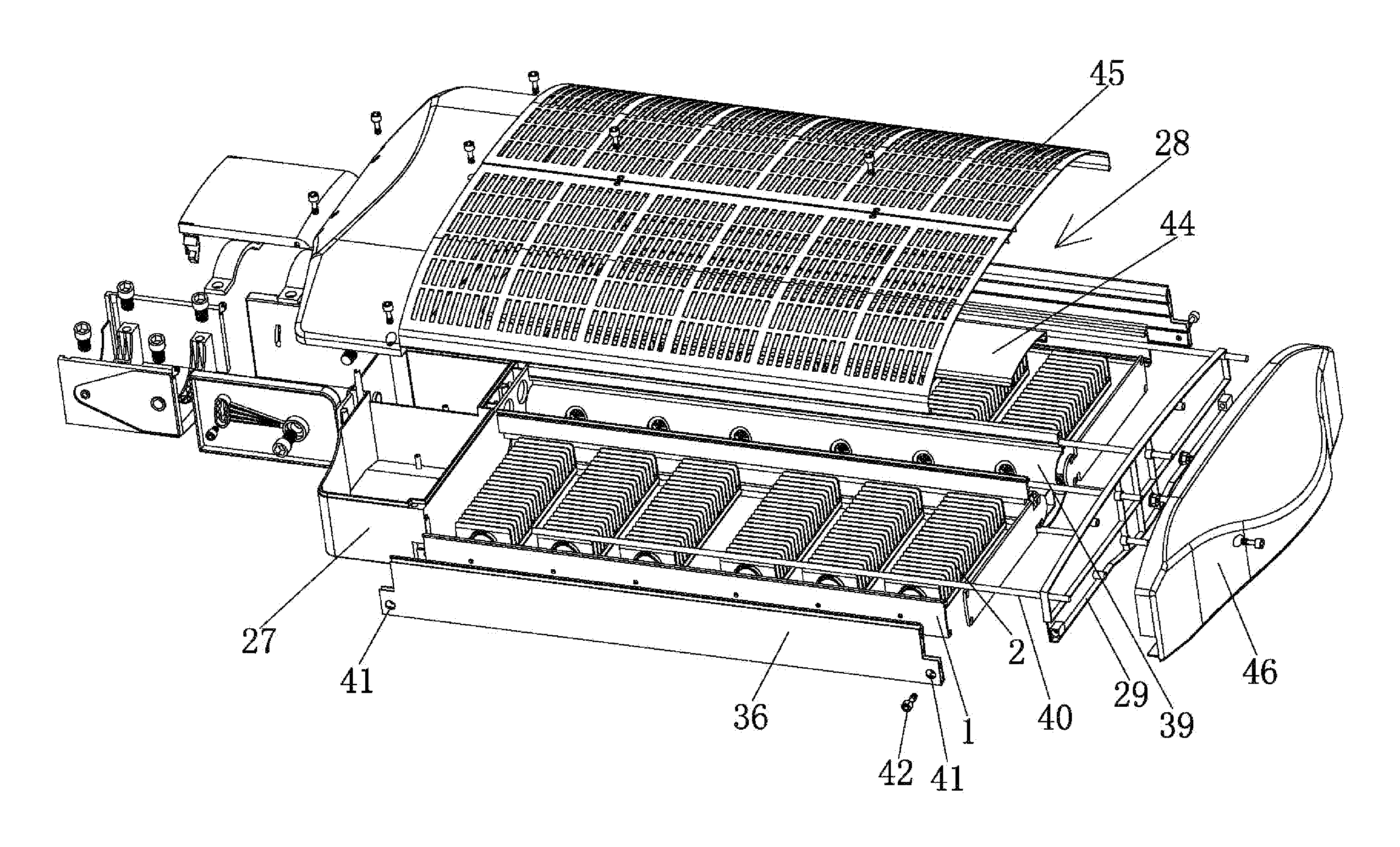
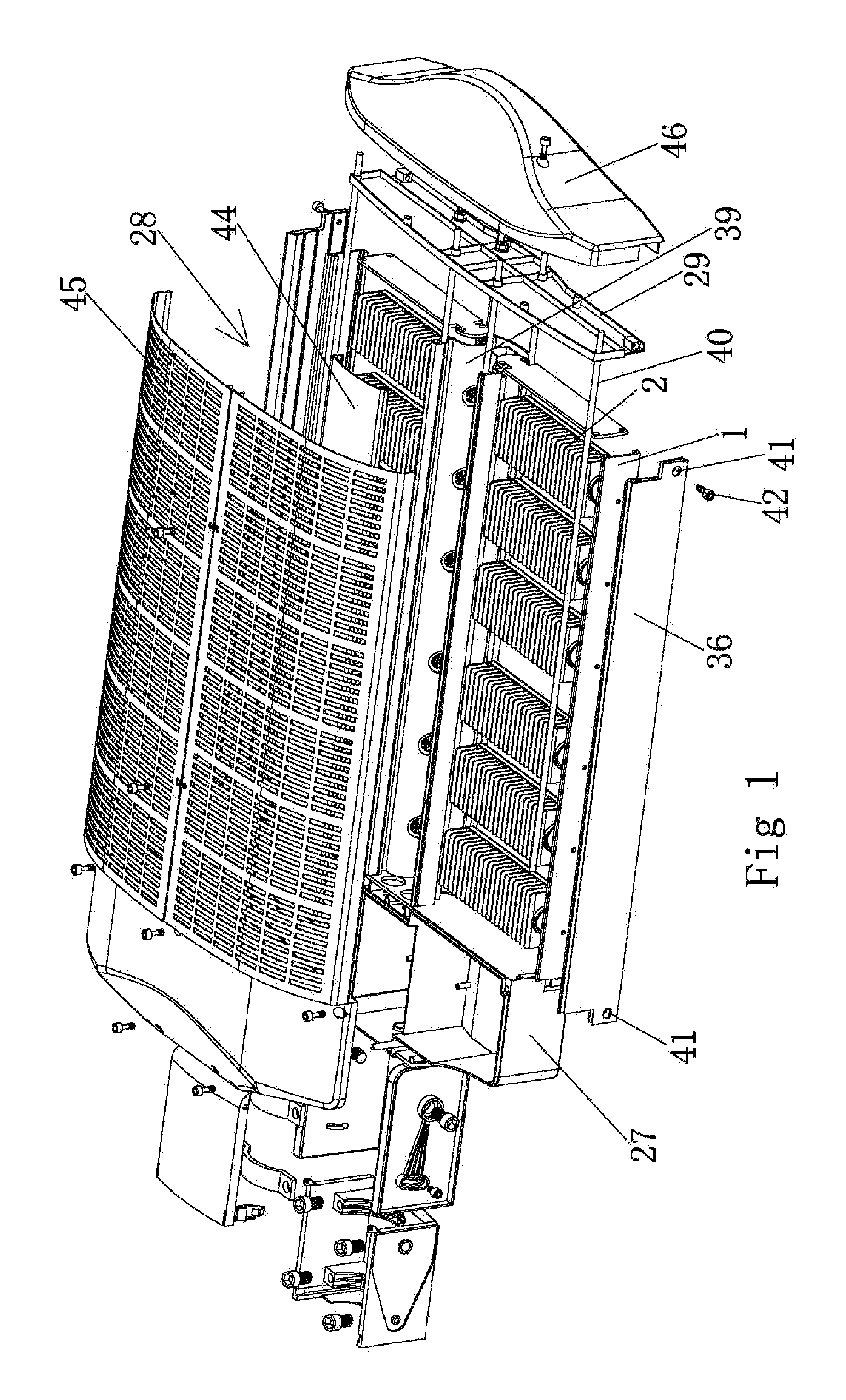
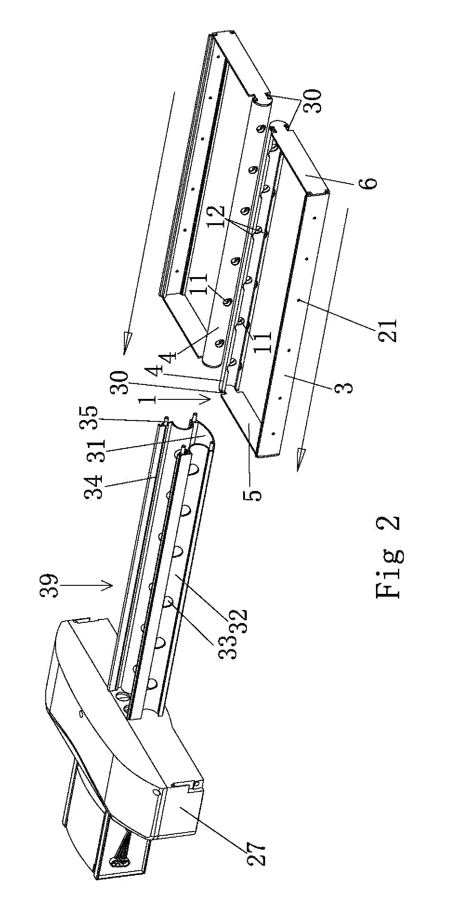
[0037]Example of implementation: as shown in FIG. 1˜6, LED street lamp base includes power source box 27 at front section, lamp holder 28 at middle section and end cap 29 at end section. Lamp holder 28 includes two frames 1 bilateral symmetrical along central line of lamp holder 28 and connecting piece 39 to connect two frames; the front and back ends of connecting piece 39 are respectively fixed and connected with power source box 27 and end cap 29 while the inside frame 1 can be turned to connect with connecting piece 39; the outside of frame 1 is connected with frame positioning unit to limit frame from turning while inside frame is set with several LED lighting module 2 side by side; LED lighting module 2 can be turned to connect with frame 1 on which module positioning module is set to limit LED lighting module 2 from turning.

[0038]The descriptions on parts and unit structure are as follows:

[0039]As shown in FIG. ...


PUM


Abstract

The present invention relates to a LED street lamp, which consists of power source box at front section, lamp holder at middle section and end cap at end section. The above mentioned lamp holder is composed of turnable framework, frame fixing unit connected with frame to limit frame rotation and several LED lighting modules installed side by side in the frame. A LED lighting module can be turned to connect with frame on which module positioning unit is set to limit the rotation of LED lighting module. For LED street lamp base of the invention, the major design part contains two bilateral symmetrical frames each of which is set with several LED lighting modules side by side. Both angles of frame and LED lighting module are adjustable of strong practicality, and so we can adjust them at any time according to practical street situation in order to ensure ideal street lighting brightness and evenness.

Description

FIELD OF THE INVENTION[0001]The present invention generally relates to street lighting, especially a framework to fix LED lighting module and a street lamp base of which the angle of LED lighting module can be adjustable.BACKGROUND OF THE INVENTION[0002]As the major application of semi-conductor lighting, LED street lamp features in long service life, strong mist penetration, and, more importantly, more energy saving than traditional street lamp.[0003]For the shortage of LED in optical performance, if you want to set LED light source on traditional lamp, it can only be done during the period of manufacture that is to carry out light distribution design according to the specific street lighting situation, namely to design lighting direction of each or each group of LED lamp, to light different street area and gain the overall lighting effect; the above mentioned street lamp can only be suitable for specific street lighting and each or each group of LED light towards fixed directions,...

Claims


Application Information

Patent Timeline
Patent Type & Authority Applications(United States)
IPC IPC(8): F21V21/14F21L4/02
CPCF21S2/005F21V29/83F21V19/02F21W2131/103F21Y2101/02F21K9/30F21V15/015F21L4/02F21V21/14F21V21/30F21V23/002Y02B20/72F21V29/507F21V29/763F21S8/086F21V14/02F21K9/20F21Y2113/00F21Y2115/10
Inventor SHEN, JINXIANG
Owner SENGLED OPTOELECTRONICS
Why Eureka
Try Eureka