
Angle-adjustable projection lamp beneficial to plant growth

A technology for plant growth and angle adjustment, applied in the field of adjustable angle floodlights, which can solve problems such as inability to adjust the angle of illumination, lack of illumination for plants, uneven lighting of plants, etc., to achieve adjustable illumination angles and wide coverage of illumination , beneficial to the growth effect

Pending Publication Date: 2021-08-27
广东泰然实业有限公司
View PDF0 Cites 3 Cited by
  • Summary
  • Abstract
  • Description
  • Claims
  • Application Information

AI Technical Summary

Problems solved by technology

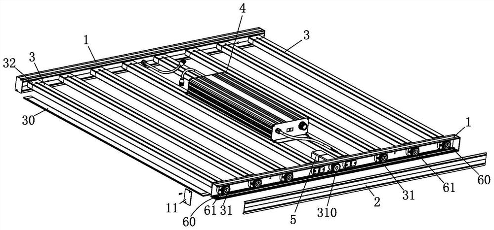
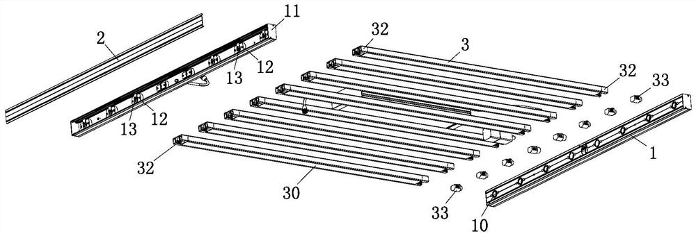
In the prior art, the plant growth lamp is generally arranged above the plants, which includes two brackets, two bracket cover plates, several light bar modules, power supply components and motors, the bracket is provided with side openings, and the back of the bracket side openings There are pivot holes on the board, the bracket cover covers the side opening of the bracket, the light bar module is provided with a light board, the two ends of the light bar module are respectively pivoted with the bracket, the motor is fixed on the back plate of the side opening of the bracket, and the power supply The components are electrically connected to the motor and the light bar module. There are problems: the angle of illumination cannot be adjusted, the direction of illumination is perpendicular to the ground, and the lighting of the plants is uneven; at the same time, due to the occlusion of the branches and leaves of the plants, the branches and leaves closer to the lights are easy to be scorched and burned. Plants in the shaded area cannot get light, which is not conducive to plant growth

Method used


Image

  • Angle-adjustable projection lamp beneficial to plant growth
  • Angle-adjustable projection lamp beneficial to plant growth
  • Angle-adjustable projection lamp beneficial to plant growth

Examples


Embodiment Construction

[0023] The implementation of the present invention will be described below with reference to the accompanying drawings and specific embodiments, and those skilled in the art can easily understand other advantages and effects of the present invention from the content disclosed in this specification.

[0024] It should be noted that the structures, proportions, sizes, etc. shown in the drawings of this specification are only used to match the content disclosed in the specification, for those who are familiar with this technology to understand and read, and are not used to limit the conditions for the implementation of the present invention , so it has no technical substantive meaning, and any modification of structure, change of proportional relationship or adjustment of size shall still fall within the scope of the disclosure of the present invention without affecting the functions and objectives of the present invention. within the range covered by the technical content. Meanw...


PUM


Abstract

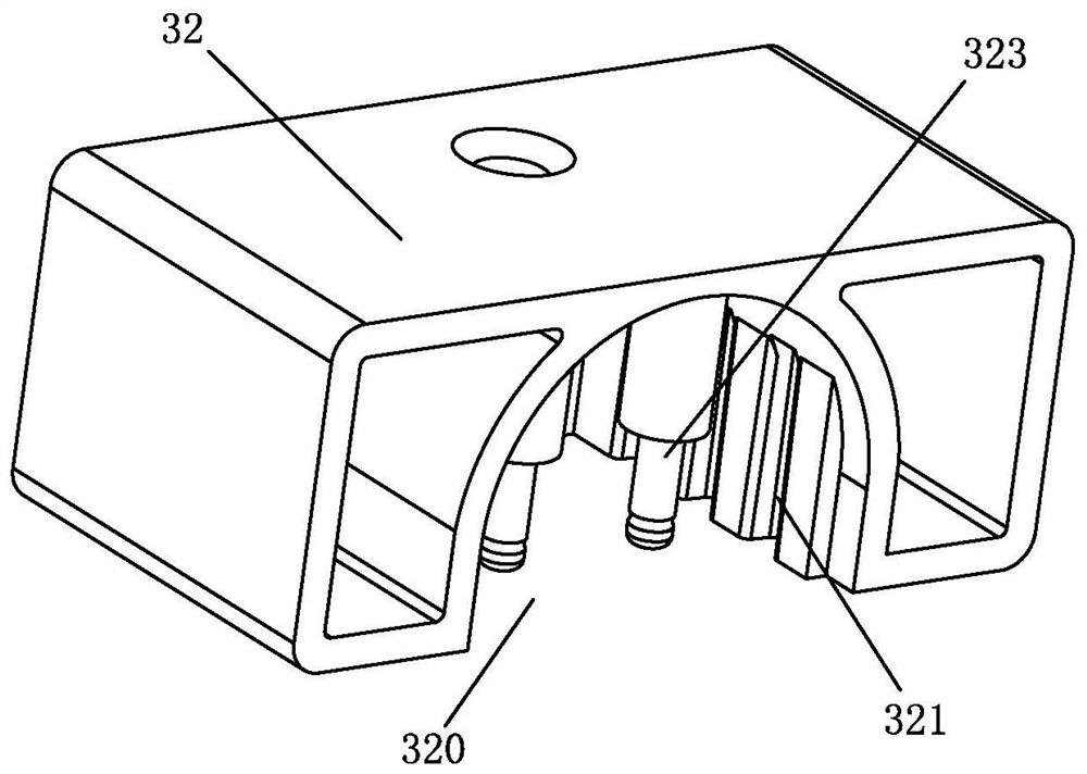
The invention discloses an angle-adjustable projection lamp beneficial to plant growth, which comprises a support, a support cover plate, a lamp strip module, a power supply assembly and a motor, the support is provided with a side opening, a pivot joint hole is formed in a side plate of the support, the support cover plate covers the side opening of the support, a lamp panel is arranged on the lamp strip module, the lamp strip module is in pivot joint with the support, and the motor is fixed to the side plate of the support. The power supply assembly is electrically connected with the motor and the lamp bar module, a transmission assembly and a driving rotating wheel are arranged in the support, a rotating shaft of the motor extends into the support and is connected with the driving rotating wheel, the driving rotating wheel is in transmission fit with the transmission assembly, the lamp bar module is provided with a driven rotating wheel, and the driven rotating wheel is arranged in the support and is in transmission fit with the transmission assembly; the driving rotating wheel and the driven rotating wheel are in transmission connection through the transmission assembly so as to drive the lamp bar module to swing, and therefore the illumination angle can be adjusted, and the device has the advantages of being simple in structure, convenient to operate and even in plant lighting.

Description

technical field [0001] The invention relates to an angle-adjustable projection lamp beneficial to plant growth. Background technique [0002] A plant growth lamp is an artificial light source, usually an electric light source, designed to stimulate plant growth by emitting an electromagnetic spectrum suitable for photosynthesis. It is used in environments where there is no natural light or supplementary light is required, for example, in winter Grow lights are used to extend the time that plants receive light when the light exposure time may not be sufficient to achieve the desired plant growth. In the prior art, the plant growth lamp is generally arranged above the plants, which includes two brackets, two bracket cover plates, several light bar modules, power supply components and motors, the bracket is provided with side openings, and the back of the bracket side openings There are pivot holes on the board, the bracket cover covers the side opening of the bracket, the lig...

Claims


Application Information

Patent Timeline
Patent Type & Authority Applications(China)
IPC IPC(8): F21S8/00F21V14/02A01G7/04
CPCA01G7/045F21S8/00F21V14/02
Inventor 朱敏欧鹏黄军华
Owner 广东泰然实业有限公司
Learn More