
Method for correcting image artifacts occuring as a result of an anti scatter grid

a technology of anti-scattering grids and image artifacts, applied in image enhancement, tomography, instruments, etc., can solve the problem of not being able to directly be used as correction images, and achieve the effect of reducing memory space requirements and reducing calibration efforts

Inactive Publication Date: 2013-06-13
SIEMENS HEALTHCARE GMBH
View PDF3 Cites 18 Cited by
  • Summary
  • Abstract
  • Description
  • Claims
  • Application Information

AI Technical Summary

Benefits of technology

The patent is about a method to fix a recorded image that has been distorted by an anti-scatter grid. The method takes into account the mechanical roughness of the system and reduces the effort required for calibration. It also reduces the amount of memory needed to store the corrected images.

Problems solved by technology

The single calibration images, as has already been mentioned, are affected by noise, so that they cannot be used directly as correction images.

Method used


Image

  • Method for correcting image artifacts occuring as a result of an anti scatter grid
  • Method for correcting image artifacts occuring as a result of an anti scatter grid
  • Method for correcting image artifacts occuring as a result of an anti scatter grid

Examples


Embodiment Construction

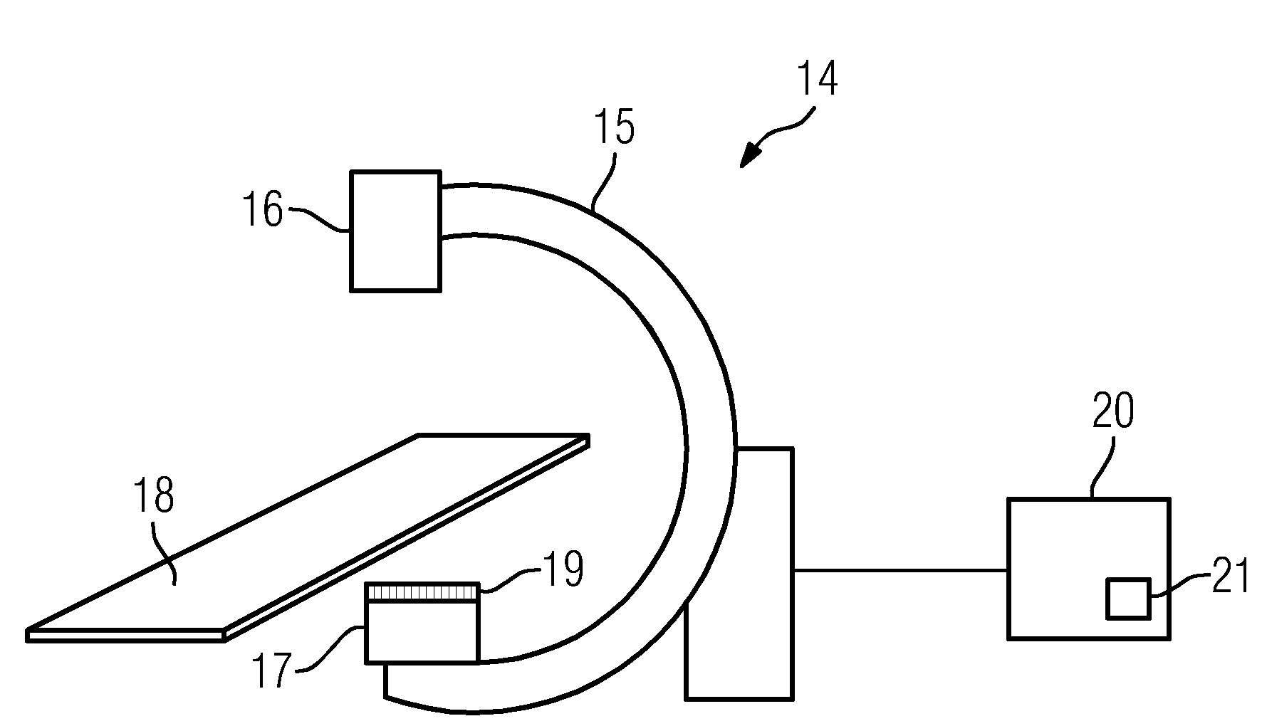
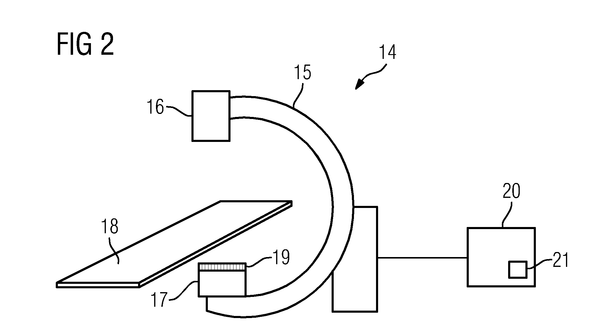
[0033]The disclosed method, thus also the embodiment shown, involves a correction of artifacts occurring as a result of an anti scatter grid connected rigidly to the x-ray detector, thus in concrete terms to a correction of the projection images which are used for a three-dimensional reconstruction such that artifacts in the three-dimensional dataset are reduced. Such artifacts, as are considered in the embodiment shown here, ultimately have different causes. In addition to the artifact patterns which are necessarily produced by shadowing by a grid of the anti-scatter grid, intensity variations can also occur if an anti-scatter grid not focused on the correct distance between the x-ray source and the x-ray detector is used or the distance between the x-ray detector and the x-ray source is not adjusted so that the focusing distance is produced. These image effects related to shadowing are independent of the actual recording geometry, wherein effects also occur in any event which are ...


PUM

PropertyMeasurementUnit
distanceaaaaaaaaaa
degree of freedomaaaaaaaaaa
computed tomographyaaaaaaaaaa

Abstract

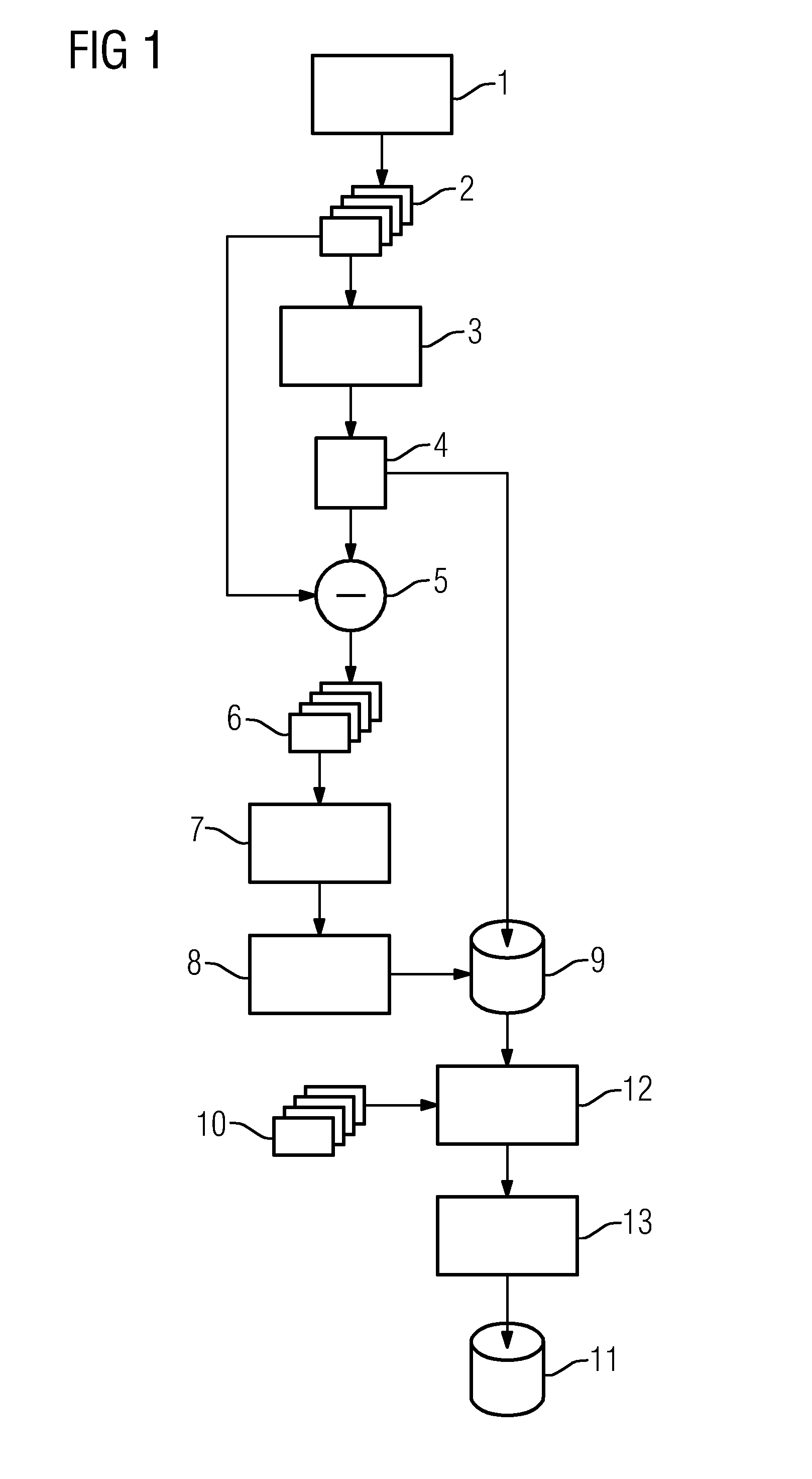
A method for correcting image artifacts is proposed. The artifacts occur as a result of an anti scatter grid connected rigidly to an x-ray detector in recording three-dimensional image datasets. Two-dimensional projection images of an object are recorded from different recording geometries for reconstruction the three-dimensional image dataset. A calibration image is recorded for each recording geometry. An average image from all recorded calibration images is established. Subtraction images are established by subtracting the average image from the corresponding calibration images. Noise is removed from the subtraction images. The subtraction images and the average image are stored. A correction image is established for each recording geometry by addition of the subtraction image assigned to the recording geometry and of the average image and is used for correcting the projection image.

Description

CROSS REFERENCE TO RELATED APPLICATIONS[0001]This application claims priority of German application No. 10 2011 088 265.0 filed Dec. 12, 2011, which is incorporated by reference herein in its entirety.FIELD OF INVENTION[0002]The application relates to a method for correction of image artifacts occurring because of an anti scatter grid connected rigidly to the x-ray detector during the recording of three-dimensional image datasets with an x-ray device with a C-arm, on which an x-ray source and the x-ray detector are arranged opposite one another, wherein two-dimensional projection images of an object are recorded from different recording geometries and used for a reconstruction of the three-dimensional image dataset. The application also relates to an x-ray device.BACKGROUND OF INVENTION[0003]C-arm x-ray devices, i.e. x-ray devices having a C-arm and on which an x-ray source and an x-ray detector are provided opposite one another are already known in the prior art. As a result of at ...

Claims


Application Information

Patent Timeline
Patent Type & Authority Applications(United States)
IPC IPC(8): G06K9/40G01N23/04
CPCG06K9/40G01N23/04G06T5/002G06T2207/20224G06T2207/10081G06T2207/20221G06T5/50A61B6/5252G06T5/70
Inventor KRUSCHEL, CHRISTIANKOHLER, CHRISTOPH
Owner SIEMENS HEALTHCARE GMBH
Learn More