Adjustable clevis assembly

Inactive Publication Date: 2013-06-13
UNITED TECH CORP
View PDF23 Cites 27 Cited by
  • Summary
  • Abstract
  • Description
  • Claims
  • Application Information

AI Technical Summary

Benefits of technology

[0007]The foregoing features and the operation of the invention will become more apparent in light of the following description and the accompanying drawings.

Problems solved by technology

Implementing such an adjustment, however, may require disassembling the bell crank system in order to position the shims onto the bolt between the clevis assembly and the bell crank body.

Method used


Image

  • Adjustable clevis assembly
  • Adjustable clevis assembly
  • Adjustable clevis assembly

Examples


Embodiment Construction

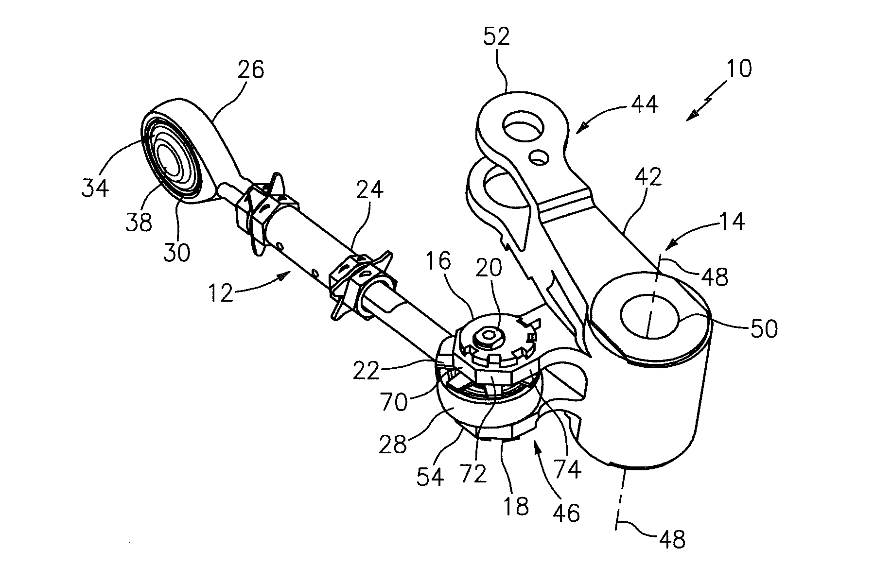
[0017]FIG. 1 illustrates an adjustable bell crank system 10 for a gas turbine engine. The bell crank system 10 may include a tie rod 12, a bell crank 14, a first adjustment sleeve 16 (e.g., a first adjustment nut), a second adjustment sleeve 18 (e.g., a second adjustment nut), a clevis pin 20 (e.g., a threaded cylindrical stud) and a tab washer 22.

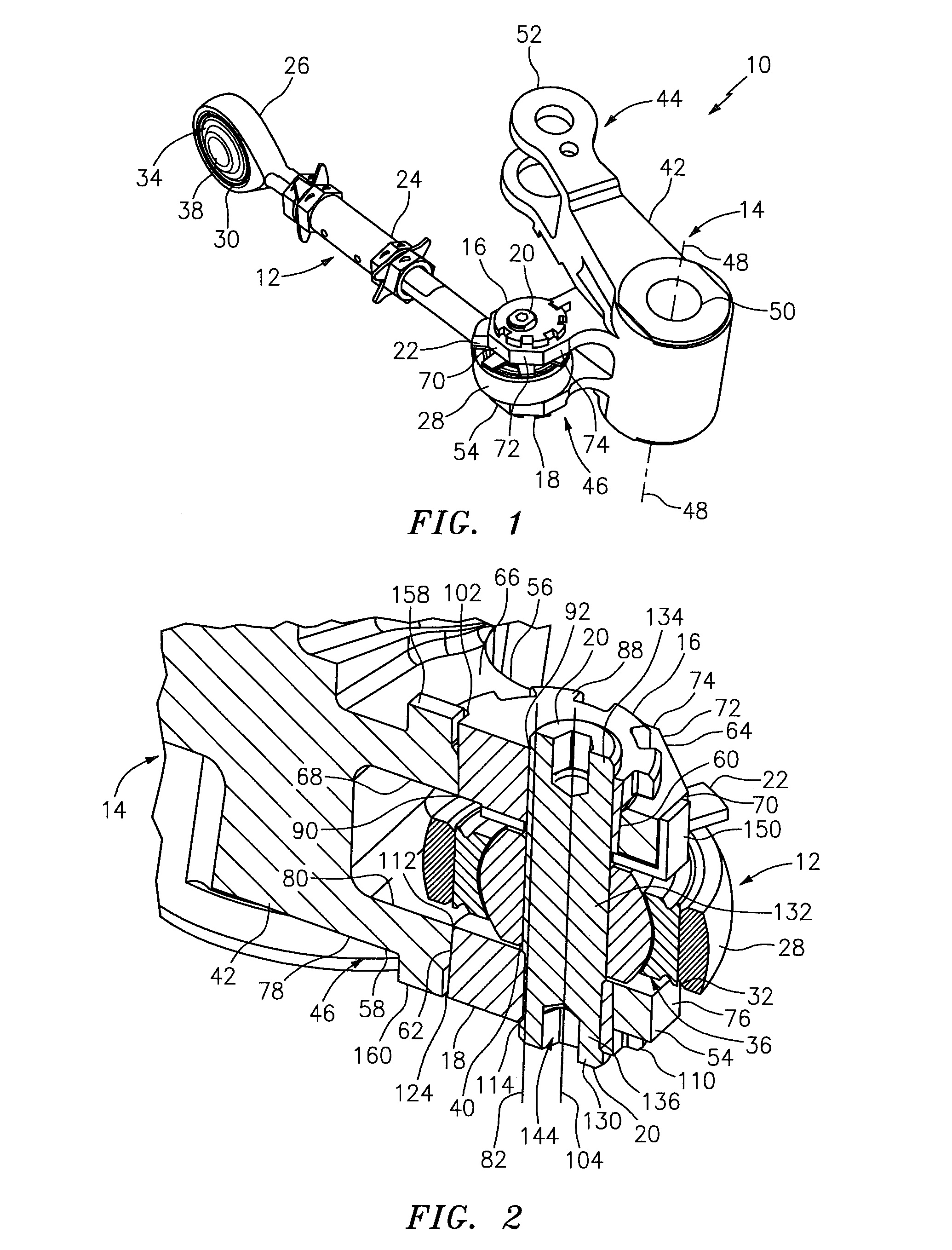
[0018]The tie rod 12 may include an adjustable tie rod shaft 24 connected between a first tie rod tongue 26 and a second tie rod tongue 28. Referring to FIGS. 1 and 2, the first tie rod tongue 26 and / or the second tie rod tongue 28 may each respectively include a pin aperture 30, 32 and a heim joint 34, 36 (e.g., a spherical rod end bearing). The pin aperture 30, 32 extends through the respective tie rod tongue 26, 28, and the respective heim joint 34, 36 is seated in the pin aperture 30, 32. Each heim joint 34, 36 includes a respective pin aperture 38, 40 extending therethrough.

[0019]Referring again to FIG. 1, the bell crank 14 may includ...


PUM


Abstract

An adjustable clevis assembly includes a clevis, a first adjustment sleeve, a second adjustment sleeve, a tongue and a clevis pin. The clevis includes a first support flange with a first sleeve aperture and a second support flange with a second sleeve aperture. The first adjustment sleeve is seated in the first sleeve aperture, and includes a first pin aperture that is eccentric relative to the first sleeve aperture. The second adjustment sleeve is seated in the second sleeve aperture, and includes a second pin aperture that is eccentric relative to the second sleeve aperture. The tongue is arranged between the first support flange and the second support flange. The clevis pin extends through the first pin aperture, the second pin aperture and a third pin aperture in the tongue.

Description

BACKGROUND OF THE INVENTION[0001]1. Technical Field[0002]The present invention relates generally to clevis assemblies and, in particular, to an adjustable clevis assembly that may be utilized, for example, in a bell crank system for a gas turbine engine.[0003]2. Background Information[0004]A gas turbine engine may include a bell crank system to actuate a mechanical engine control system such as, for example, a compressor bypass valve, an adjustable stator vane, etc. Such a bell crank system may include a clevis assembly that connects a tie rod to a bell crank body. The clevis assembly may be connected to the bell crank body with a bolt and nut. The aim length of the clevis assembly may be adjusted by arranging one or more shims between the clevis assembly and the bell crank body. Implementing such an adjustment, however, may require disassembling the bell crank system in order to position the shims onto the bolt between the clevis assembly and the bell crank body.SUMMARY OF THE DISC...

Claims


Application Information

Patent Timeline
Patent Type & Authority Applications(United States)
IPC IPC(8): F16C11/04
CPCF16C2360/23F16C3/28Y10T403/32221F16C23/043F16C11/02F16C11/045F16C11/0614F16C11/0695F16C23/10
Inventor WIECKO, STANLEYPUDVAH, BERNARD W.GASMEN, EUGENE C.
Owner UNITED TECH CORP
Why Eureka
Try Eureka