Lock device

a technology of locking device and lock cylinder, which is applied in the direction of cylinder locks, building locks, constructions, etc., can solve the problems of increasing the difficulty of reading out the lock cylinder, increasing the difficulty of reading out the unlocking position, and the possibility of providing an additional increment, so as to achieve simple and inexpensive manufacturing and high security

Active Publication Date: 2013-06-20
VOLKSWAGEN AG
View PDF11 Cites 5 Cited by
  • Summary
  • Abstract
  • Description
  • Claims
  • Application Information

AI Technical Summary

Benefits of technology

[0007]It is therefore an object of the invention to provide a lock device that can be manufactured both simply and inexpensively and that offers especially high security against reading-out of the unlocking positions.

Problems solved by technology

Although this tumbler in its rest position does not contribute to locking the lock cylinder since it is in its unlocking position, it not only makes reading out the lock cylinder more difficult, but also offers the possibility of providing an additional increment.
This further increases the difficulty of reading out the unlocking positions.

Method used


Image

  • Lock device
  • Lock device
  • Lock device

Examples


Embodiment Construction

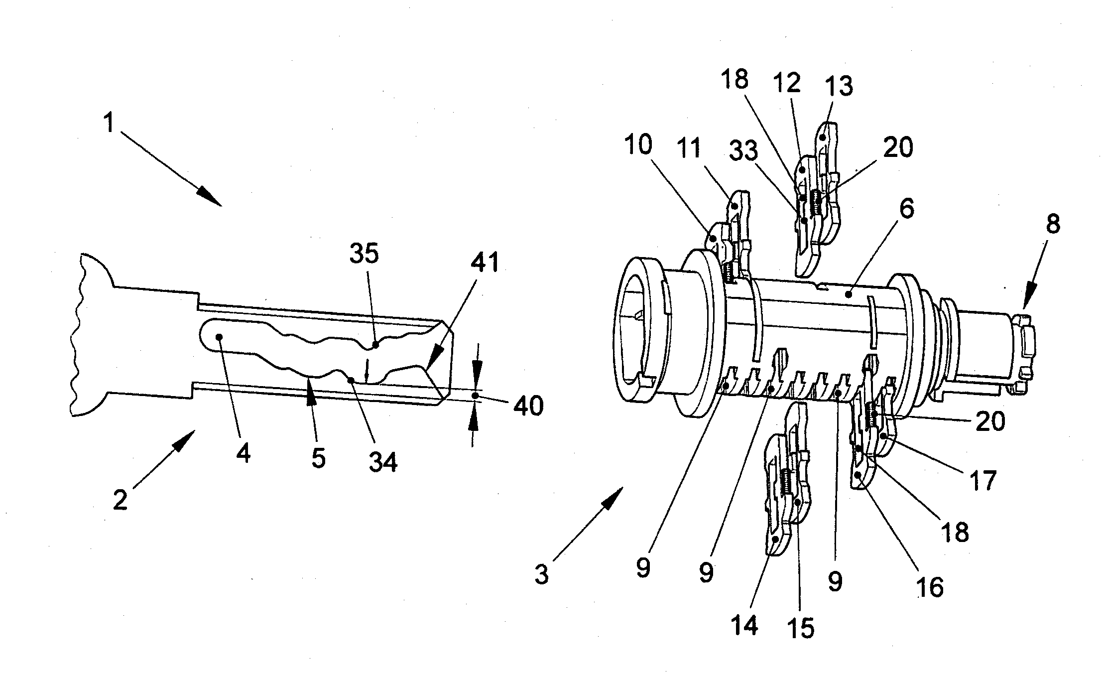
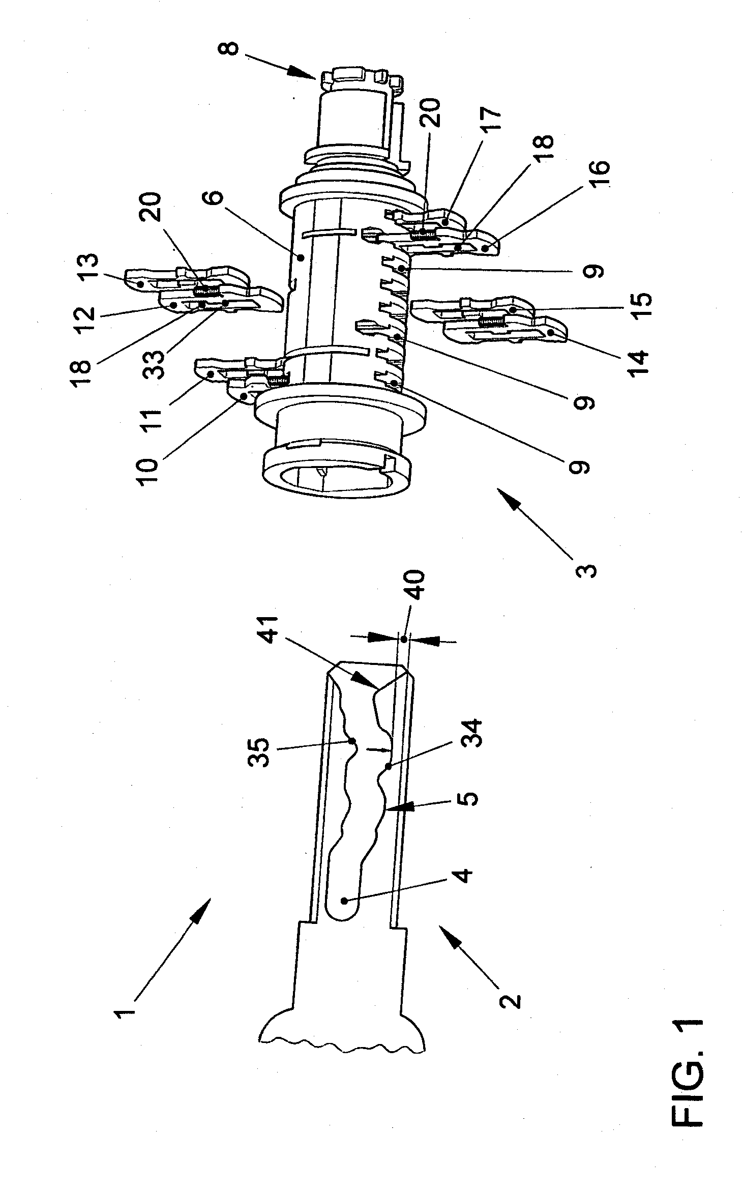
[0025]FIG. 1 shows a perspective, exploded view of a lock device 1, comprising a flat key 2 and a lock cylinder 3. The flat key 2 has a recess 4 in its lateral surface that forms a control gate 5. The control gate 5 defines the steps and the increments by which each of the tumblers is displaced, wherein the increments are uniformly distributed over the entire maximum displacement travel.

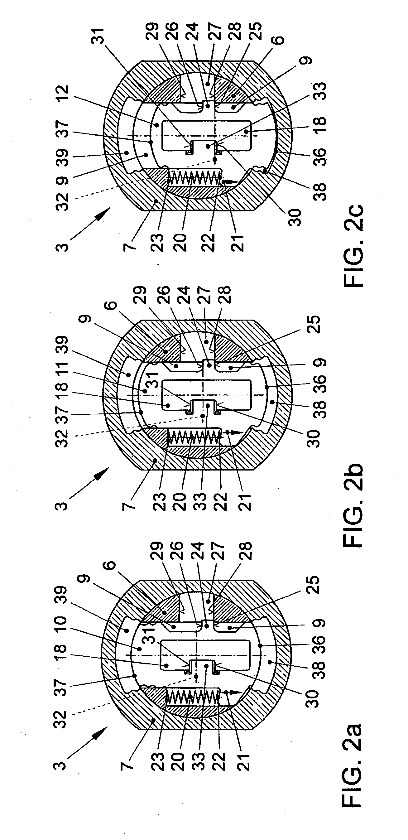
[0026]The lock cylinder 3 has one cylinder core 6 shown, which is rotatably supported in a cylinder housing 7 that is shown in the other figures. At one end, the cylinder core 6 has rotary carrier component 8 that serves to transmit a rotary motion or rotation of the cylinder core 6 to a lock mechanism that is not shown here. At the opposite end from the rotary carrier component 8, the cylinder core 6 is open to accommodate the flat key 2.

[0027]Moreover, the cylinder core 6 is designed to be largely hollow or implemented as a cylindrical sleeve. Perpendicular to its axis of rotation, the cylinder cor...


PUM


Abstract

A lock device having a lock cylinder and a flat key having a control gate. The lock cylinder has a cylinder housing and a cylinder core rotationally supported in the cylinder housing and a plurality of plate-shaped tumblers that are supported in the cylinder core so as to be radially slidable with respect to the rotational axis of the cylinder core and which each have a key opening and are at least partially pushed by the spring load into a locking channel of the cylinder housing in order to lock the lock cylinder when the flat key is removed and which are slid into an unlocking position by the control cam guided in the control gate when the key is inserted. At least one stop is associated with each of the tumblers in order to limit the sliding path to conceal the unlocking position.

Description

[0001]This nonprovisional application is a continuation of International Application No. PCT / EP2011 / 003996, which was filed on Aug. 10, 2011, and which claims priority to German Patent Application No. DE 10 2010 033 904.0, which was filed in Germany on Aug. 10, 2010, and which are both herein incorporated by reference.BACKGROUND OF THE INVENTION[0002]1. Field of the Invention[0003]The invention relates to a lock device with a lock cylinder and a flat key having a control gate.[0004]2. Description of the Background Art[0005]Conventional lock devices are known from the prior art. High demands are placed on such lock devices with regard to security against break-in, so that simple reading out of the unlocking positions of the different tumblers should be prevented. A tumbler typically has locking edges on both sides that project into a specific locking channel of the cylinder housing in the locking position. In this design, the locking edges are designed such that they are flush with t...

Claims


Application Information

Patent Timeline
Patent Type & Authority Applications(United States)
IPC IPC(8): E05B29/00
CPCE05B19/0058E05B29/0033E05B29/00Y10T70/7599Y10T70/7695Y10T70/7785
Inventor HAVEMANN, JOERGWINKLER, HELGE
Owner VOLKSWAGEN AG
Why Eureka
Try Eureka