Support Arm Structure

Inactive Publication Date: 2013-06-27
HUANG MING HUA
View PDF9 Cites 26 Cited by
  • Summary
  • Abstract
  • Description
  • Claims
  • Application Information

AI Technical Summary

Benefits of technology

[0004]The primary object of the present invention is to provide an improved support arm structure that can mitigate the dra

Problems solved by technology

Thus, the display 30 cannot be raised or lower too much, thereby causing inconvenience for persons having a higher or shorter height.
C

Method used


Image

  • Support Arm Structure
  • Support Arm Structure
  • Support Arm Structure

Examples


Embodiment Construction

[0020]To achieve the purpose of the present invention, the technical means and the structure implemented thereby will be detailed below with reference to FIGS. 3-7 of the accompanying drawings.

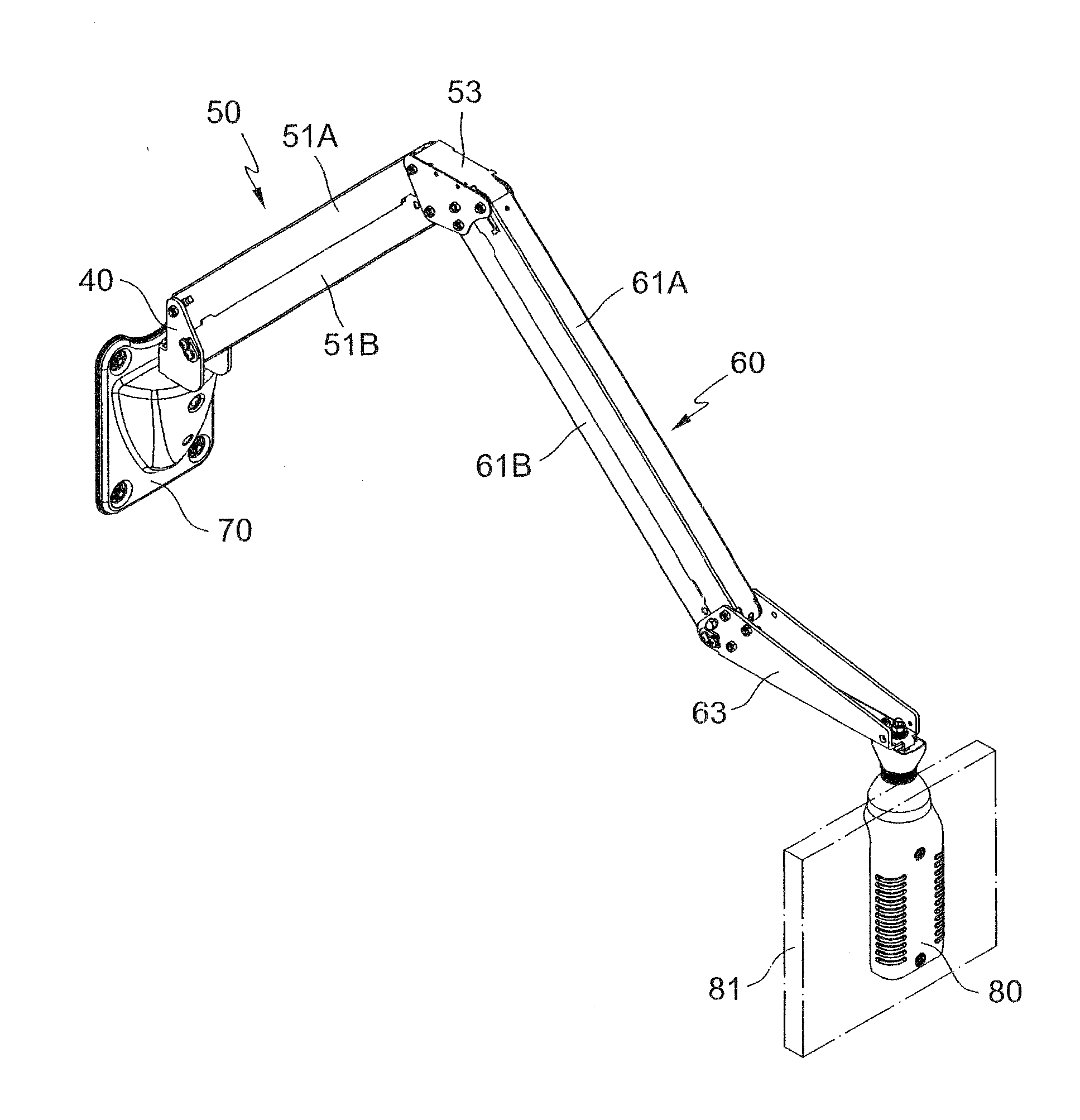
[0021]As shown in FIG. 3, an improved support arm structure according to one embodiment of the present invention generally comprises a base joint 40, a primary arm assembly 50, an extension arm assembly 60 pivotally connected to the primary arm assembly 50.

[0022]The base joint 40 is provided for connecting the primary arm 50 assembly to a wall bracket 70 that can be fixed onto a wall, wherein the base joint 40 is provided with a pin 41 (see FIG. 4) pivotally fitted in the wall bracket 70 to allow the base joint 40 to be rotated horizontally about the pin 41.

[0023]As shown in FIGS. 4-7, the primary support arm assembly 50 includes an upper aim 51A and a lower arm 51B. A rear end of the upper arm 51A is pivotally connected to the base joint 40 through a set of fixing elements 52A inserted with a...


PUM


Abstract

An improved support arm structure comprises a base joint, a primary arm assembly, and an extension arm assembly pivotally connected to the primary arm assembly; wherein the base joint is provided for connecting the primary arm assembly to a wall bracket; a rear end of the primary arm assembly is connected to the base joint; a front end of the primary arm assembly is connected to a middle joint; a first spring is provided in the primary arm assembly; a rear end of the extension arm assembly is connected to the middle joint; a front end of the extension arm assembly is connected to a front elongated joint; a second spring is provided in the extension arm assembly; whereby the support arm structure can be adjusted to any angles according to the requirements of a user and can be operated conveniently and safely.

Description

TECHNICAL FIELD OF THE INVENTION[0001]The present invention relates to an improved arm structure and, more particularly, to an arm structure that can mitigate the drawbacks of conventional arm structures and can be operated conveniently and safely to meet the angle requirements of a user.DESCRIPTION OF THE PRIOR ART[0002]As shown in FIGS. 1 and 2, a conventional support aim structure 10 comprises a primary arm 11, a mounting base 12, and an extension aim 13. The rear end of the primary arm 11 is pivotally connected to the mounting base 12 by using a pin 20 to allow the primary arm 11 to be rotated horizontally relative to the mounting base 12. The front end of the primary arm 11 is pivotally connected to the extension arm 13 by using another pin 20 inserted into a joint to allow the extension arm 13 to be rotated horizontally relative to the joint, wherein the joint allows the extension arm 13 to be rolled in vertical direction. Furthermore, the front end of the extension arm 13 is ...

Claims


Application Information

Patent Timeline
IPC IPC(8): H05K7/00F16M13/00
CPCF16M11/08F16M2200/044F16M11/24F16M11/2092
Inventor HUANG, MING HUA
Owner HUANG MING HUA
Why Eureka
Try Eureka