Combustion Apparatus

Active Publication Date: 2013-06-27
RINNAI CORP
View PDF12 Cites 4 Cited by
  • Summary
  • Abstract
  • Description
  • Claims
  • Application Information

AI Technical Summary

Benefits of technology

The invention involves a device that prevents air from interfering with the flow of air in a duct. This is achieved by using an auxiliary suction opening that is located near the outlet of the duct. The air from this opening is sucked into the duct through the space surrounding the outlet, preventing it from interfering with the main air flow. This reduces the flow resistance in the duct and ensures a steady air flow. The device also includes a flange portion that prevents dust and debris from clogging the suction opening, improving its reliability. Additionally, the invention suggests using multiple auxiliary suction openings to ensure continued suppression of low-frequency resonant sounds, even if some of the openings are closed by clogging.

Problems solved by technology

The air from the auxiliary suction opening thus interferes with the suction air flow in the air suction duct.
In addition, in case the auxiliary suction opening is closed by clogging with dirt, the low-frequency resonant sounds in the range of 400 Hz to 800 Hz can no longer be suppressed.

Method used


Image

  • Combustion Apparatus
  • Combustion Apparatus
  • Combustion Apparatus

Examples


Embodiment Construction

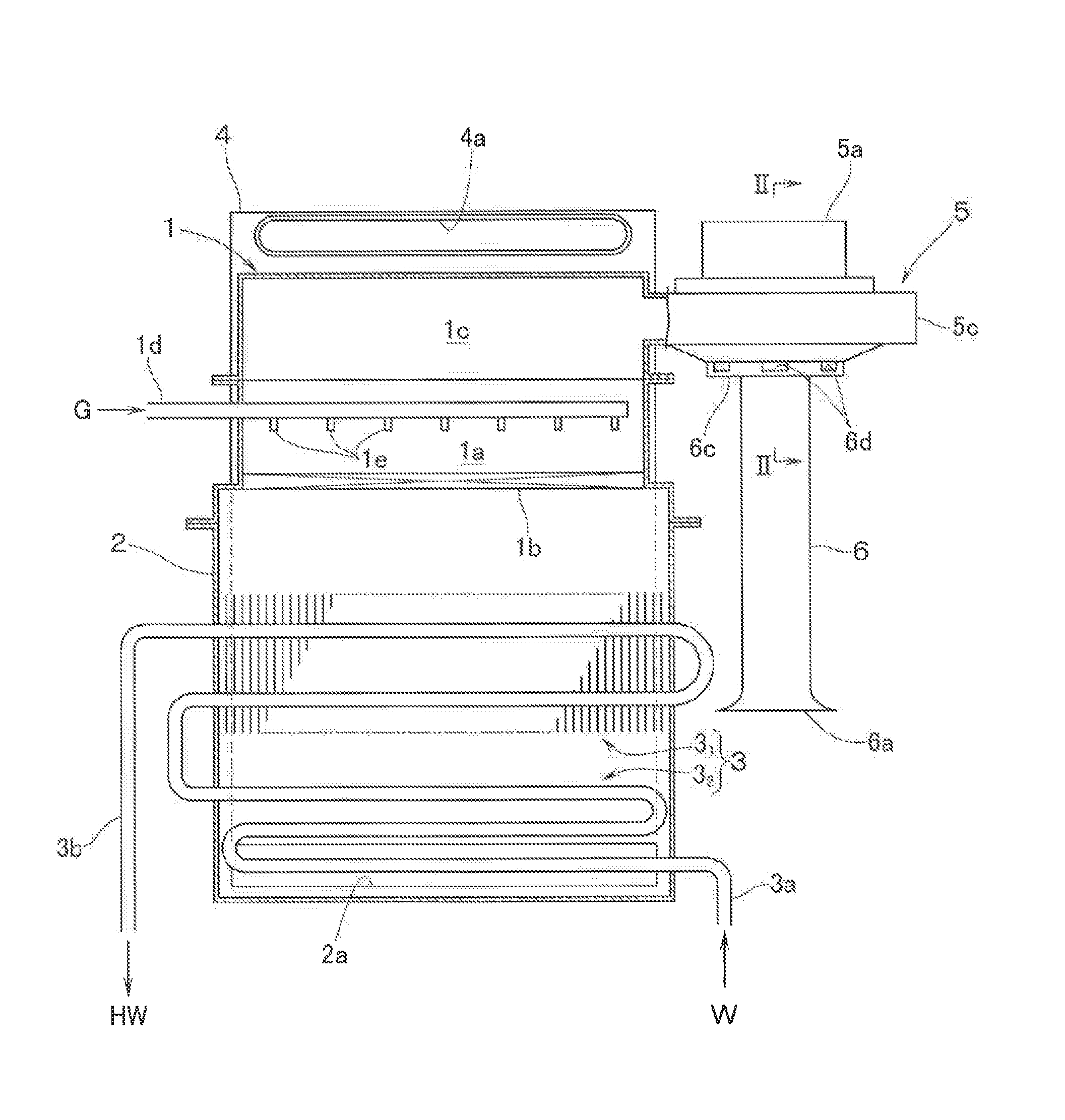
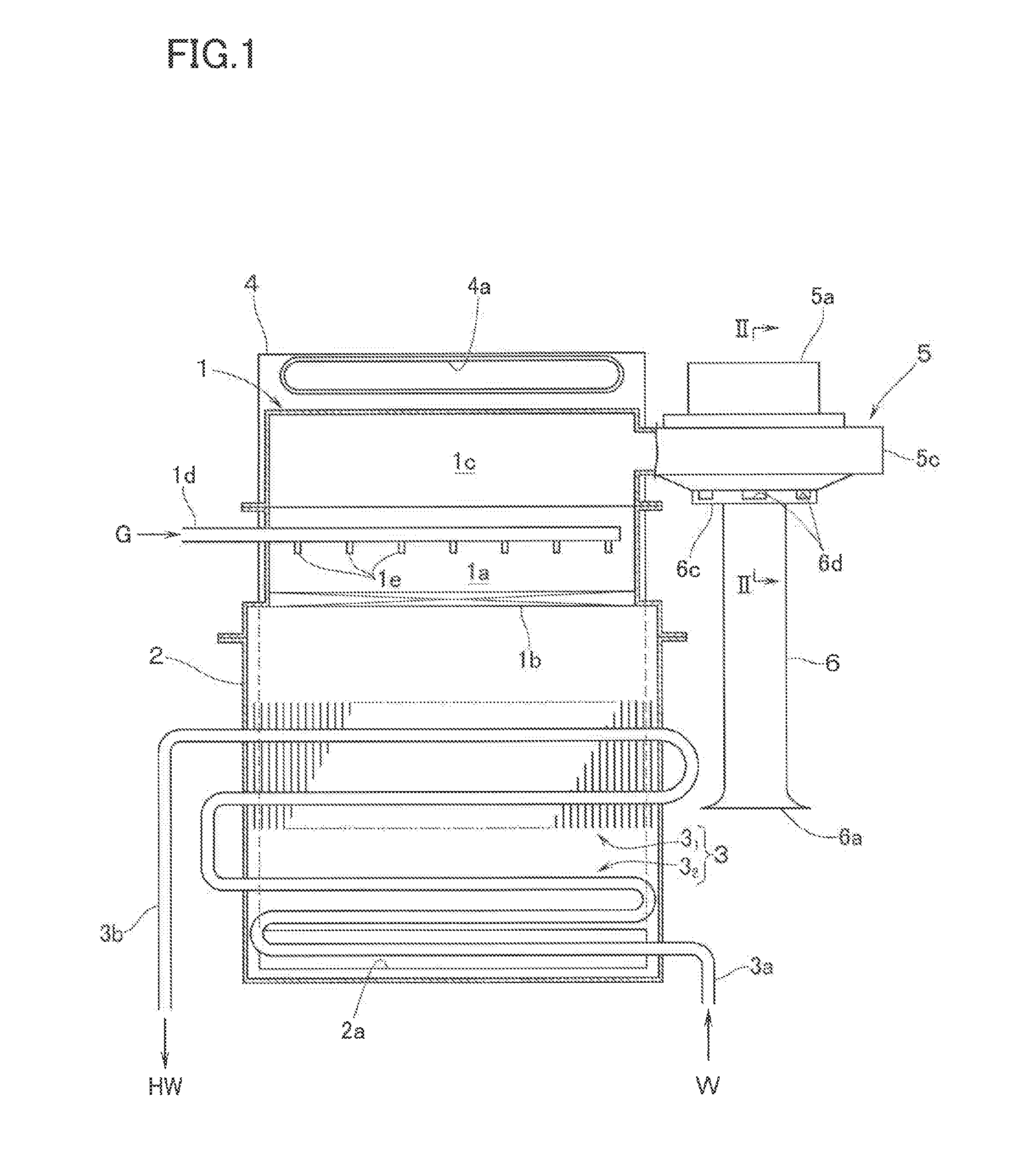
[0018]FIG. 1 shows a combustion apparatus having heat source equipment for supplying hot water according to an embodiment of this invention. This combustion apparatus is made up of: a burner 1 on an upper portion of the combustion apparatus; a combustion box 2 which is connected to the bottom of the burner 1 so as to house therein a heat exchanger 3 which supplies hot water by heating with the combustion gas from the burner 1; an exhaust duct 4 which is in fluid communication with the combustion box 2 through an opening 2a which is formed in a lower rear portion of the combustion box 2 so as to serve as an exhaust passage which is elongated upward from the opening 2a; and a fan 5 which supplies the burner 1 with combustion air.

[0019]The heat exchanger 3 has: a first heat exchanger 31 of sensible heat recovery type which is housed in an upper part of the combustion box 2; and a second heat exchanger 32 of latent heat recovery type which is housed in a lower part of the combustion box...


PUM


Abstract

A combustion apparatus has a burner, a combustion box containing therein a heat exchanger, an exhaust passage in fluid communication with the combustion box, a fan for supplying the burner with combustion air, and a predetermined length of air suction duct in fluid communication with a suction opening formed in a fan casing. The air suction duct has: on a downstream end thereof, an outlet cylindrical portion which is smaller in diameter than a diameter of the suction opening in the fan casing and which lies opposite to the suction opening; and a flange portion which overhangs radially outward from a perimeter of the air suction duct adjacent to the outlet cylindrical portion into contact with that peripheral portion of the fan casing which forms the suction opening. The flange portion is provided with an auxiliary suction opening in fluid communication with a space surrounding the outlet cylindrical portion.

Description

BACKGROUND OF THE INVENTION[0001]1. Field of the Invention[0002]The present invention relates to a combustion apparatus which is provided with a burner, a combustion box containing therein a heat exchanger which is heated by combustion gas from the burner, an exhaust passage in fluid communication with the combustion box, and a fan for supplying the burner with combustion air.[0003]2. Description of the Related Art[0004]This kind of combustion apparatus is likely to give rise to low-frequency resonant sounds below 100 Hz. This is due to the fact that an open pipe equivalent length (the length corresponding to an open pipe whose both ends are free ends) from a suction opening formed in a fan casing which houses therein fan impellers to an exhaust port on a downstream end of the exhaust passage becomes the length that corresponds to a multiple of half wavelength of frequency components below 100 Hz that are contained in the combustion noises generated by combustion vibrations, thereby...

Claims


Application Information

Patent Timeline
IPC IPC(8): F23M99/00
CPCF23M99/005F23M20/005F23M20/00
Inventor TANAKA, FUMIOAKAGI, KAZUYUKIOKAMOTO, HIDEO
Owner RINNAI CORP
Why Eureka
Try Eureka