Magnetic resonance system, operating method and control device to generate t2-weighted images using a pulse sequence with very short echo times

a pulse sequence and pulse sequence technology, applied in the field of magnetic resonance system, operating method and control device to generate t2weighted images, can solve the problems of not being able to generate tsub>2 and not being able to generate tsub>2, and achieve the effect of suppressing quickly and well

Inactive Publication Date: 2013-07-04
SIEMENS HEALTHCARE GMBH
View PDF7 Cites 13 Cited by
  • Summary
  • Abstract
  • Description
  • Claims
  • Application Information

AI Technical Summary

Benefits of technology

[0020]The sequence control unit can preferably be realized in the form of software on a suitable programmable control device with corresponding memory capabilities. The radio-frequency transmission device, the gradient system interface and the radio-frequency reception device can be at least partially realized in the form of software units, with other units of these components are being purely hardware units, for example the radio-frequency amplifier, a gradient pulse generation device of the gradient system interface, or an analog / digital converter of the radio-frequency reception device etc. A realization largely in software, in particular of the sequence control unit, has the advantage that magnetic resonance system control devices that have already previously been in use can be retrofitted in a simple manner via a software update in order to operate in the manner according to the invention. The above object also can be achieved by computer-readable instructions / commands stored in a transportable storage medium and / or provided for transmission via a network, that can be loaded directly into a memory of a programmable magnetic resonance system control device, with program segments in order to execute all steps of the method according to the invention when the program is executed in the control device.
[0021]As noted above, in a preferred embodiment of the method according to the invention the second magnetic resonance radio-frequency pulse is already used as an excitation pulse, and the acquisition of raw data takes place in a short time interval immediately after emission of the second magnetic resonance radio-frequency pulse. As used herein a “short time interval” means a time period that is so short that the transverse magnetization of even substances with short T2 has not yet fallen too sharply, such that sufficient signal of even these substances is captured in the FID and the substances contribute to the contrast. The interval between the last magnetic resonance radio-frequency pulse and the beginning of the acquisition of raw data is advantageously at most 200 μs, preferably 100 μs. It preferably amounts to at least 50 μs, more preferably approximately 70 μs (for example with a tolerance of 2 μs above and below). The interval is calculated from the middle of the pulse to the beginning of the data acquisition.
[0022]In this method, another hard excitation pulse is thus initially applied at a defined point in time before the subsequent hard excitation pulse, and the effects of the two pulses are counter to one another. This leads overall to the situation that all substances are excited by the first pulse, but then the transverse magnetization of substances with short T2 is strongly relaxed between the pulses, in contrast to which the transverse magnetization of substances with long T2 barely changes between the pulses. The flip angles of the substances with long T2 are consequently flipped back again to zero by the second pulse, in contrast to which the substances with short T2 are newly excited. If the raw data are then acquired in FID in a short interval after this, only the substances with short T2 have a transverse magnetization differing from zero and are therefore visible in the image. Substances with long T2 are thus suppressed quickly and well in a simple manner.

Problems solved by technology

However, since given very short times the signals of all substances decay approximately equally (see echo time TE1 in FIG. 1), no T2 contrast can be generated with these.
In particular, with the present UEZ sequences it is consequently also not possible to generate T2 contrasts in which substances with long T2 are markedly brighter in the image than substances with short T2, as they are required for many clinical questions.

Method used


Image

  • Magnetic resonance system, operating method and control device to generate t2-weighted images using a pulse sequence with very short echo times
  • Magnetic resonance system, operating method and control device to generate t2-weighted images using a pulse sequence with very short echo times
  • Magnetic resonance system, operating method and control device to generate t2-weighted images using a pulse sequence with very short echo times

Examples


Embodiment Construction

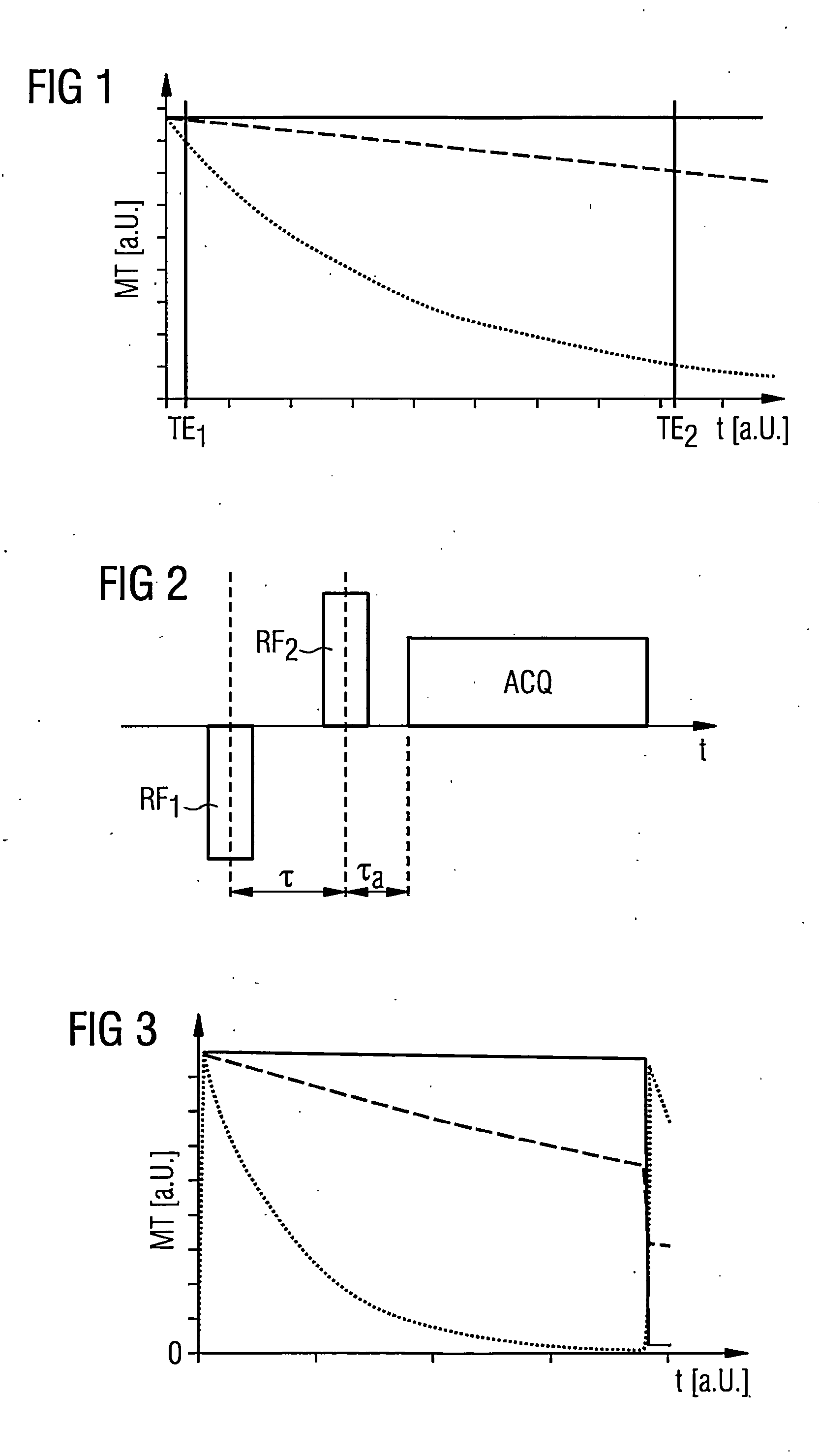
[0044]The contents of FIG. 1 has already been explained above.

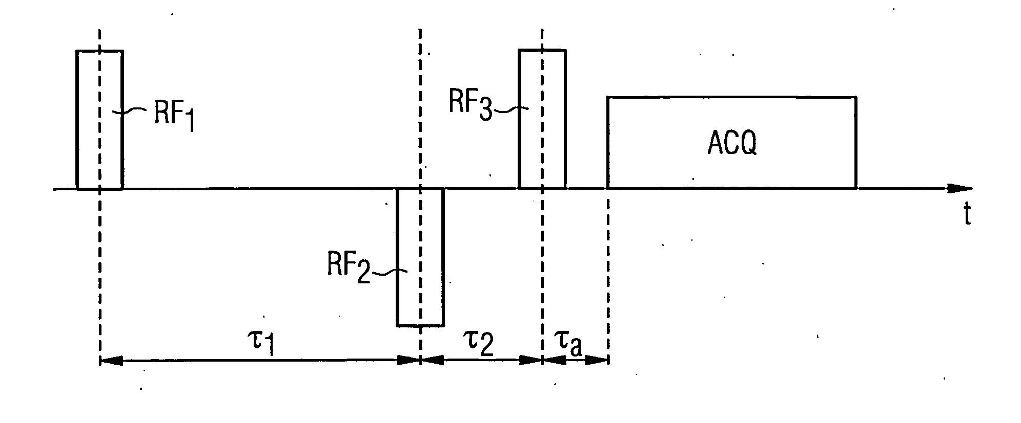
[0045]The excitation and acquisition curve for a first variant of the method according to the invention in the form of a very simplified pulse sequence on only one axis is schematically presented in the pulse diagram in FIG. 2. The first two pulses are the magnetic resonance radio-frequency pulses RF1, RF2. The block shown after this on the time axis symbolizes the acquisition ACQ of the raw data. This acquisition ACQ takes place as a measurement of the FID signal. Since the two magnetic resonance radio-frequency pulses RF1, RF2 are not slice-selective, here the complete spatial coding takes place during the raw data acquisition in that gradient fields are switched in various directions. However, this procedure is known in principle to those skilled in the art and therefore does not need to be explained in detail herein.

[0046]In the method shown in FIG. 2, a pulse with the flip angle −α (i.e. with a phase rotated by 180° ...


PUM


Abstract

In a method to control a magnetic resonance system to generate magnetic resonance exposures of an examination subject, a first magnetic resonance radio-frequency pulse with a pulse length of at most 50 μs is initially emitted in a volume region of the examination subject. At least one second magnetic resonance radio-frequency pulse, whose phase is essentially rotated by 180° relative to the first magnetic resonance radio-frequency pulse, with a pulse length of at most 50 μs, is emitted in the same volume region of the examination subject in a predetermined time interval immediately after the first magnetic resonance radio-frequency pulse. An acquisition of raw data from the volume region of the examination subject then takes place. Furthermore, a control device for operating a magnetic resonance system as well as a magnetic resonance system with such a control device to implement such a method, are described.

Description

BACKGROUND OF THE INVENTION[0001]1. Field of the Invention[0002]The present invention concerns a method to control a magnetic resonance system to generate magnetic resonance exposures of an examination subject, as well as a control device for a magnetic resonance system and a magnetic resonance system with which such a method can be implemented.[0003]2. Description of the Prior Art[0004]In order to obtain magnetic resonance exposures—i.e. image data—from a region of the inside of a body of an examination subject, the body or the body part that is to be examined, must initially be exposed to an optimally homogeneous, static basic magnetic field (most often designated as a B0 field). The nuclear spins in the body are thereby aligned parallel to the direction of the B0 field (typically designated as the z-direction). Moreover, radio-frequency pulses (also called “magnetic resonance radio-frequency pulses” in the following) are radiated into the examination subject with radio-frequency ...

Claims


Application Information

Patent Timeline
Patent Type & Authority Applications(United States)
IPC IPC(8): G01R33/54
CPCG01R33/4816G01R33/54G01R33/5602A61B5/055
Inventor GRODZKI, DAVID
Owner SIEMENS HEALTHCARE GMBH
Why Eureka
Try Eureka