
Shield connector

a shield connector and connector technology, applied in the direction of coupling device connection, two-part coupling device, electrical apparatus, etc., can solve the problem of increasing the cost of metal molds, and achieve the effect of reducing costs, improving workability, and easy mation

Inactive Publication Date: 2013-07-04
YAZAKI CORP
View PDF9 Cites 8 Cited by
  • Summary
  • Abstract
  • Description
  • Claims
  • Application Information

AI Technical Summary

Benefits of technology

The invention provides a solution to connect two male and female shield connectors without the need for different outer terminal configurations, which results in cost savings and improved workability. The outer terminals are sharable between the connectors, allowing the metal mold and applicator to be shared. The connectors are designed to prevent deviation during mating. The cylindrical portion of the outer terminals includes a stopper portion that ensures a stable mating state and prevents upward-downward deviation.

Problems solved by technology

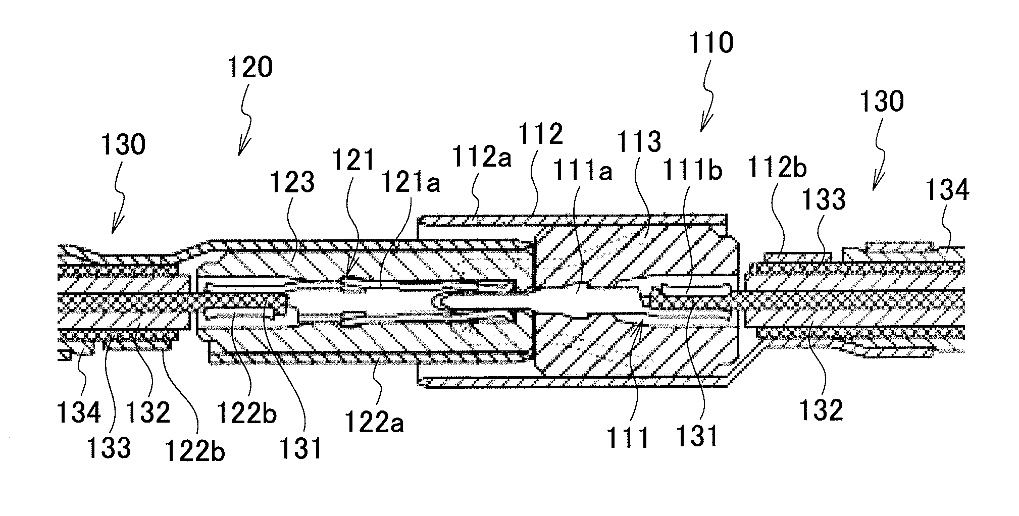
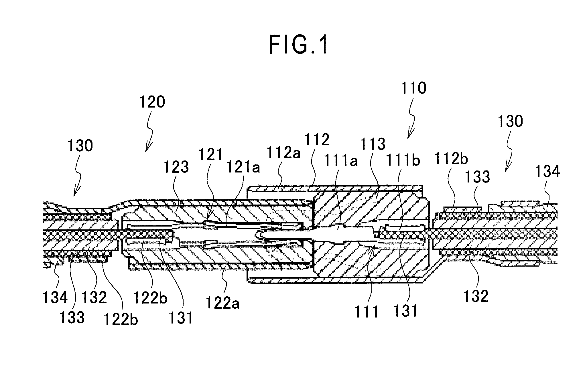
This caused such a problems as that not only special metal molds for preparing the outer terminals 112, 122 are individually needed, but also the metal mold cost is increased.

Method used


Image

  • Shield connector
  • Shield connector
  • Shield connector

Examples


Embodiment Construction

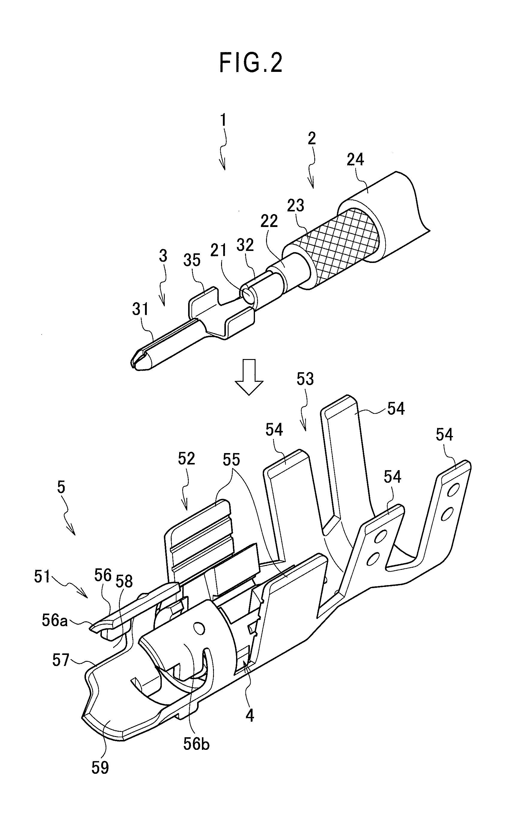
[0030]An embodiment of the present invention will be explained with reference to FIG. 2 to FIG. 11.

[0031]As shown in FIG. 11, a shield connector 1 is mated and electrically connected with a mating connector 11, to thereby allow shield electric cables 2 (connected respectively with the connectors 1, 11) to be connected with each other. The mating of the connectors 1, 11 is implemented with outer terminals 5, 15 of the shield connector 1 and mating connector 11 having the same configuration and with the outer terminals 5, 15 of the connectors 1, 11 reversed upside down (refer to FIG. 5, FIG. 6 and FIG. 11). As the mating connector 11, one like the shield connector 1 is used.

[0032]As shown in FIG. 2, a shield electric cable 2 is connected to the shield connector 1. As shown in FIG. 2 and FIG. 11, the shield electric cable 2 has a coaxial structure formed by a central core wire 21 formed by twining together a plurality of conductive wires, an inner cover 22 made of an insulation resin a...


PUM


Abstract

An inner terminal connected to a terminal of a core wire and provided with an electric connecting portion electrically connected with a mating terminal is received in an inner housing. The inner housing is incorporated into an outer terminal. The outer terminal is mated with a mating connector in such a state as that the shield member is connected to the outer terminal and the electric connecting portion of the inner terminal is positioned in the outer terminal. The outer terminal has the same configuration as that of an outer terminal of the mating connector, thus making the outer terminals sharable between male and female connectors.

Description

BACKGROUND OF THE INVENTION[0001]1. Field of the Invention[0002]The present invention relates to a shield connector used for allowing shield electric cables to be connected with each other by mating a male connector and a female shield with each other.[0003]2. Description of the Related Art[0004]FIG. 1 shows a conventional shield connector described in Japanese Patent Unexamined Publication No. 2011-34773 (Patent Literature 1) and Japanese Patent Unexamined Publication No. 2011-65882 (Patent Literature 2). A shield connector is formed with a male shield connector 110 and a female shield connector 120. The male and female shield connectors 110, 120 are used for connecting shield electric cables 130.[0005]The shield electric cable 130 has a coaxial structure formed with a core wire 131 made by twining together a plurality of wires, an inner cover 132 made of an insulation covering the core wire 131, a shield member 133 made of a braided wire covering an outer periphery of the inner co...

Claims


Application Information

Patent Timeline
Patent Type & Authority Applications(United States)
IPC IPC(8): H01R13/6593
CPCH01R13/6593H01R24/44H01R13/213H01R9/0518H01R13/28
Inventor KANDA, HIDENORIMIYAWAKI, KOJI
Owner YAZAKI CORP
Learn More