Touch panel and a manufacturing method thereof

a technology of touch panel and manufacturing method, which is applied in the field of touch panel, can solve the problems that the conventional design of the touch panel cannot meet the requirements, and achieve the effect of reducing the peripheral area, increasing the available touch area, and reducing the area of the peripheral area

Active Publication Date: 2013-07-11
TPK TOUCH SOLUTIONS (XIAMEN) INC
View PDF3 Cites 3 Cited by
  • Summary
  • Abstract
  • Description
  • Claims
  • Application Information

AI Technical Summary

Benefits of technology

[0008]The present disclosure provides a touch panel and a manufacturing method thereof. The touch panel comprises a plurality of conductive wire axes disposed on a touch area along a second axis and extended to a first peripheral area, wherein the plurality of conductive wire axes lead out peripheral leads of first sensing electrode axes along the second axis such that the peripheral leads that connect the first sensing electrode axes and peripheral leads that connect second sensing electrode axes are centralized at one side of the touch area, thereby reducing area of the peripheral area of the touch panel and effectively increasing area of the available touch area and increasing visible area on the touch panel.
[0011]To sum up, for a touch panel and a manufacturing method provided in the embodiments of the present disclosure, a plurality of conductive wire axes are disposed on a touch area along a second axis and are extended to a first peripheral area, wherein the plurality of conductive wire axes lead out peripheral leads of first sensing electrode axes along the second axis such that the peripheral leads that connect the first sensing electrode axes and peripheral leads that connect second sensing electrode axes are concentrated in the first peripheral area, thereby reducing area of the peripheral area of the touch panel and effectively increasing areas of the available touch area and a visible area on the touch panel.

Problems solved by technology

However, if a designer would like to reduce size of a peripheral area of a touch panel, for example, to maximize size of the available touch area, the conventional design of a touch panel can not meet the requirement.

Method used


Image

  • Touch panel and a manufacturing method thereof
  • Touch panel and a manufacturing method thereof
  • Touch panel and a manufacturing method thereof

Examples


first embodiment

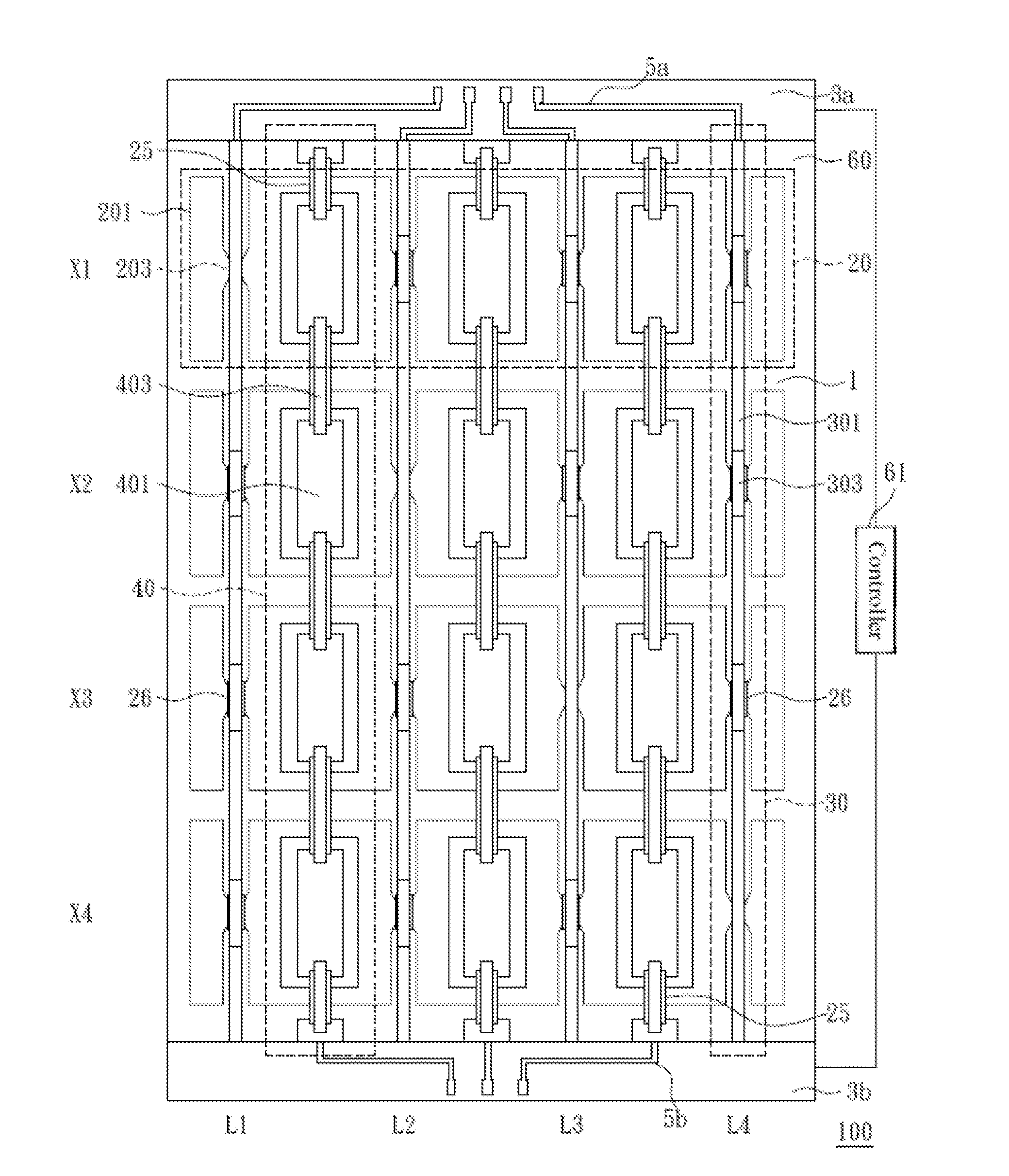
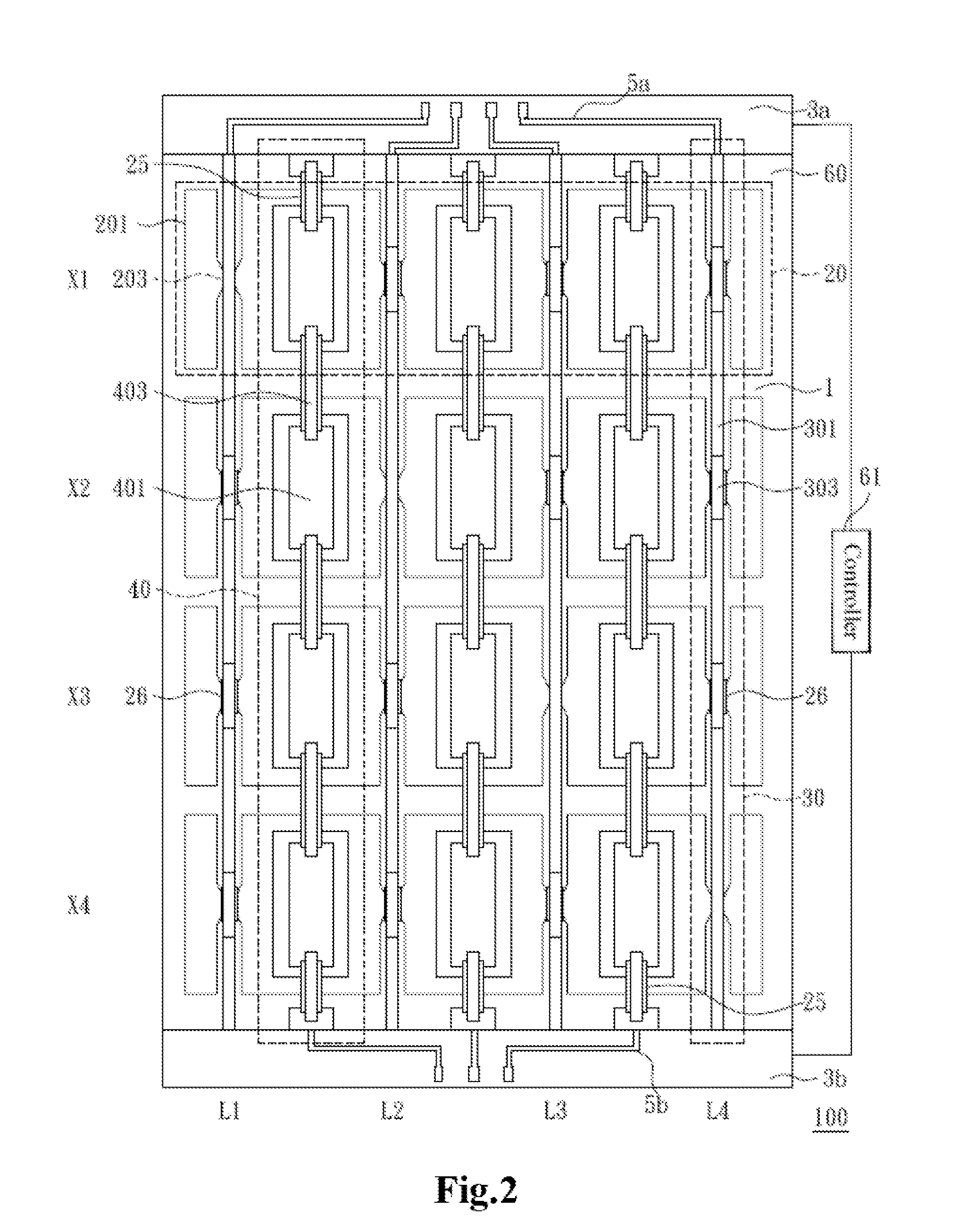
[0021]FIG. 2 is a schematic structure view of a touch panel in accordance with the present disclosure. A touch panel 100 has a touch area 1 and a first peripheral area 3a. The touch panel 100 comprises a plurality of first sensing electrode axes 20, a plurality of second sensing electrode axes 40, and a plurality of conductive wire axes 30. The first sensing electrode axes 20 and the second sensing electrode axes 40 are disposed on the touch area 1 along a first axis and a second axis respectively. The first sensing electrode axes 20 are electrically insulated from the second sensing electrode axes 40. The conductive wire axes 30 are disposed on the touch area 1 along the second axis and are extended to the first peripheral area 3a, wherein any two of the conductive wire axes 30 are electrically connected to different first sensing electrode axes 20, and wherein the first peripheral area 3a is located at a first side of the touch area 1.

[0022]Specifically, in the present embodiment,...

second embodiment

[0051]FIGS. 11˜12 are schematic views illustrating a method for manufacturing a touch panel in accordance with the present disclosure. The manufacturing method in the present embodiment is used to form the touch panel 100 shown in FIG. 3 correspondingly.

[0052]First manufacturing process of the present embodiment is approximately identical to the first manufacturing process of the first embodiment, as shown in FIG. 6. For conciseness, no more description is made herein.

[0053]In a second manufacturing process, as shown in FIG. 11, a plurality of first insulation blocks 25 and a plurality of second insulation blocks 26 are formed, wherein each of the first insulation blocks 25 is disposed on the first electrodes 201 between the adjacent second electrodes 401 and each of the second insulation blocks 26 is disposed on the first conductive wire 203 at an insulation point such that conductive wire axes 30 and first sensing electrode axes 20 to be formed subsequently are electrically connec...

third embodiment

[0056]FIGS. 13˜14 are schematic views illustrating a method for manufacturing a touch panel in accordance with the present disclosure. The manufacturing method in the present embodiment is used to form the touch panel 100 shown in FIG. 4 correspondingly.

[0057]First and second manufacturing processes of the present embodiment are approximately identical to the first and second manufacturing processes of the first embodiment, as shown in FIG. 6 and FIG. 7. Thus, no more description is made herein.

[0058]Difference between the present embodiment and the first embodiment at least lies in that: as shown in FIG. 13, in a third manufacturing process, an insulation layer 77 is formed on the first electrodes 201, the first conductive wires 203, the second electrodes 401, and the conductive wire segments 301. There are a plurality of first through-holes 771 and a plurality of second through-holes 772 on the surface of the insulation layer 77, wherein the first through-holes 771 correspond to t...


PUM

PropertyMeasurementUnit
areaaaaaaaaaaa
conductiveaaaaaaaaaa
sizeaaaaaaaaaa

Abstract

The present disclosure relates to a touch technology and more particularly, to a touch panel and a manufacturing method thereof. The touch panel comprises a plurality of first sensing electrode axes, a plurality of second sensing electrode axes, and a plurality of conductive wire axes. The first sensing electrode axes are disposed along a first axis. The second sensing electrode axes are disposed along a second axis and electrically insulated from the first sensing electrode axes. The plurality of conductive wire axes are disposed along the second axis and extended to the first peripheral area. Any two of the conductive wire axes are electrically connected to different first sensing electrode axes. According to the touch panel and the manufacturing method provided in the present disclosure, areas of the available touch area and a visible area on the touch panel can be effectively increased.

Description

BACKGROUND OF THE INVENTION[0001]This Application claims the benefit of the People's Republic of China Application No. 201210009306.4, filed on Jan. 6, 2012.FIELD OF THE INVENTION[0002]The present disclosure relates to touch technology. More particularly, the present disclosure relates to a touch panel and a manufacturing method thereof.[0003]DESCRIPTION OF THE RELATED ART[0004]In recent years, electronic devices such as mobile phones, laptops and palmtops are widely used with a touch display screen, wherein the touch display screen disposed on the electronic devices acts both as an input and output interface. A user can control the electronic device with the help of the touch display screen and control functions of the electronic device correspondingly.[0005]Generally, the touch display screen displays image information on the display screen or performs a preset function according to a touch location sensed by the touch panel. Touch input modes of conventional touch panels include ...

Claims


Application Information

Patent Timeline
Patent Type & Authority Applications(United States)
IPC IPC(8): G06F3/041H01R43/00
CPCG06F3/044Y10T29/49117G06F2203/04111G06F3/04164G06F3/0443G06F3/0446G06F3/0448G06F3/0412G06F2203/04112
Inventor JIANG, YAU-CHENWU, DEFAXIE, YANJUNYAN, JIANBIN
Owner TPK TOUCH SOLUTIONS (XIAMEN) INC
Why Eureka
Try Eureka