Ventilation Mask with Integrated Piloted Exhalation Valve

a technology of exhalation valve and ventilation mask, which is applied in the field of ventilation mask, can solve the problems of high non-compliance rate, high patient pressure, and high non-compliance rate of cpap therapy, and achieves reduced flow, less bulk, and high functional dead space

Active Publication Date: 2013-07-18
BREATHE TECHNOLOGIES INC
View PDF0 Cites 25 Cited by
  • Summary
  • Abstract
  • Description
  • Claims
  • Application Information

AI Technical Summary

Benefits of technology

[0014]One of the primary benefits attendant to including the valve inside the mask is that it provides a path for patient-expired CO2 to exit the system without the need for a dual-limb patient circuit, and without the disadvantages associated with a single-limb patient circuit, such as high functional dead space. For instance, in applications treating patients with sleep apnea, having the valve inside the mask allows patients to wear the mask while the treatment pressure is turned off without risk of re-breathing excessive CO2.
[0015]Another benefit for having the valve inside the mask is that it allows for a significant reduction in the required flow generated by the ventilator for ventilating the patient since a continuous vented flow for CO2 washout is not required. Lower flow in turn allows for the tubing size to be significantly smaller (e.g., 2-9 mm ID) compared to conventional ventilators (22 mm ID for adults; 8 mm ID for pediatric). However, this configuration requires higher pressures than the patient's therapeutic pressure to be delivered by the ventilator. In this regard, pressure from the ventilator is significantly higher than the patient's therapeutic pressure, though the total pneumatic power delivered is still smaller than that delivered by a low pressure, high flow ventilator used in conjunction with a vented patient circuit and interface. One obvious benefit of smaller tubing is that it provides less bulk for patient and / or caregivers to manage. For today's smallest ventilators, the bulk of the tubing is as significant as the bulk of the ventilator. Another benefit of the smaller tubing is that is allows for more convenient ways of affixing the mask to the patient. For instance, the tubing can go around the patient's ears to hold the mask to the face, instead of requiring straps (typically called “headgear”) to affix the mask to the face. Along these lines, the discomfort, complication, and non-discrete look of the headgear is another significant factor leading to the high non-compliance rate for CPAP therapy. Another benefit to the smaller tubing is that the mask can become smaller because it does not need to interface with the large tubing. Indeed, large masks are another significant factor leading to the high non-compliance rate for CPAP therapy since, in addition to being non-discrete, they often cause claustrophobia. Yet another benefit is that smaller tubing more conveniently routed substantially reduces what is typically referred to as “tube drag” which is the force that the tube applies to the mask, displacing it from the patient's face. This force has to be counterbalanced by headgear tension, and the mask movements must be mitigated with cushion designs that have great compliance. The reduction in tube drag in accordance with the present invention allows for minimal headgear design (virtually none), reduced headgear tension for better patient comfort, and reduced cushion compliance that results in a smaller, more discrete cushion.
[0016]The mask of the present invention may further include a heat and moisture exchanger (HME) which is integrated therein. The HME can fully or at least partially replace a humidifier (cold or heated pass-over; active or passive) which may otherwise be included in the ventilation system employing the use of the mask. The HME is positioned within the mask so as to be able to intercept the flow delivered from a flow generator to the patient in order to humidify it, and further to intercept the exhaled flow of the patient in order to capture humidity and heat for the next breath. The HME can also be used as a structural member of the mask, adding a cushioning effect and simplifying the design of the cushion thereof.

Problems solved by technology

However, this configuration requires higher pressures than the patient's therapeutic pressure to be delivered by the ventilator.
Along these lines, the discomfort, complication, and non-discrete look of the headgear is another significant factor leading to the high non-compliance rate for CPAP therapy.
Indeed, large masks are another significant factor leading to the high non-compliance rate for CPAP therapy since, in addition to being non-discrete, they often cause claustrophobia.

Method used


Image

  • Ventilation Mask with Integrated Piloted Exhalation Valve
  • Ventilation Mask with Integrated Piloted Exhalation Valve
  • Ventilation Mask with Integrated Piloted Exhalation Valve

Examples


Embodiment Construction

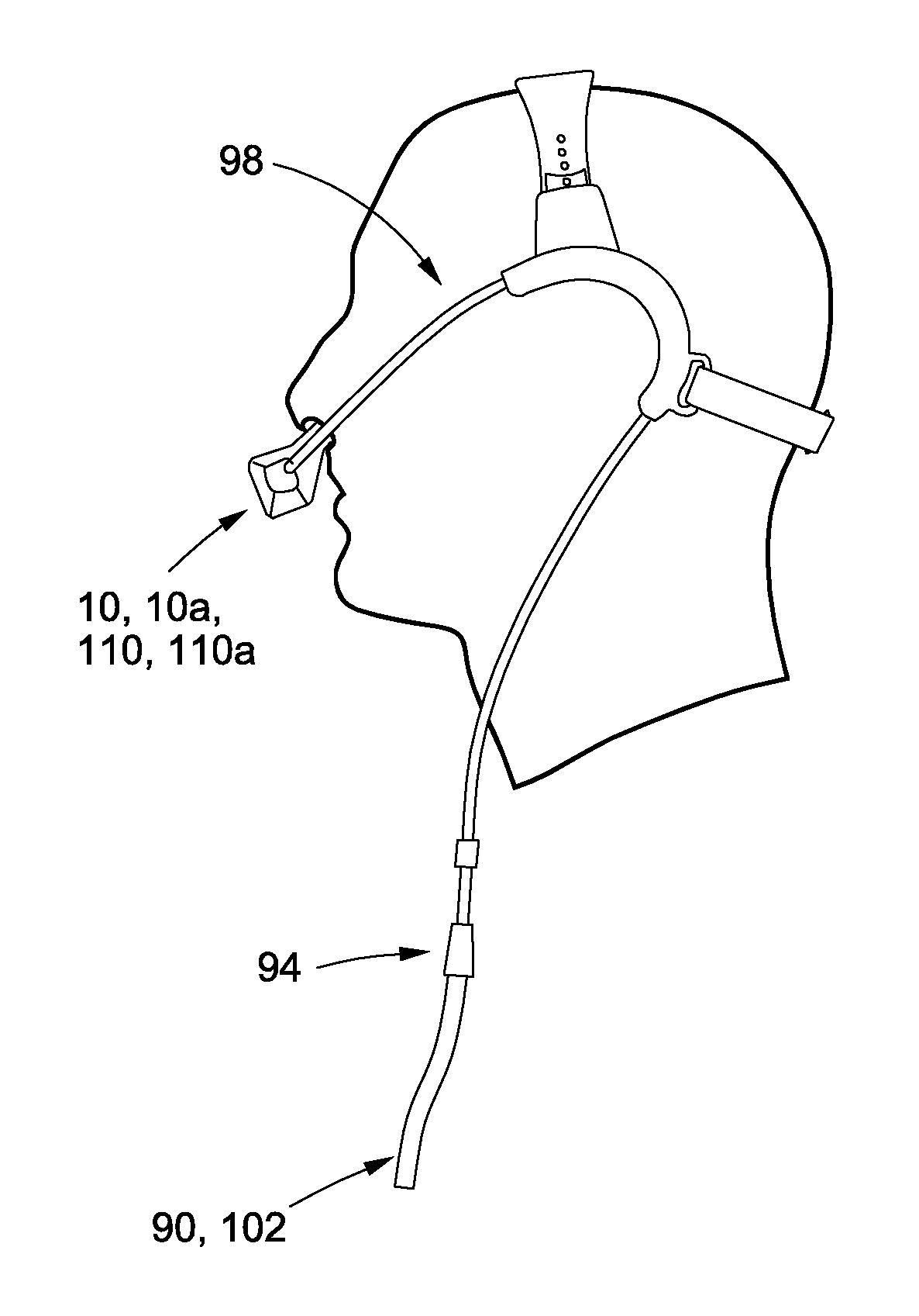
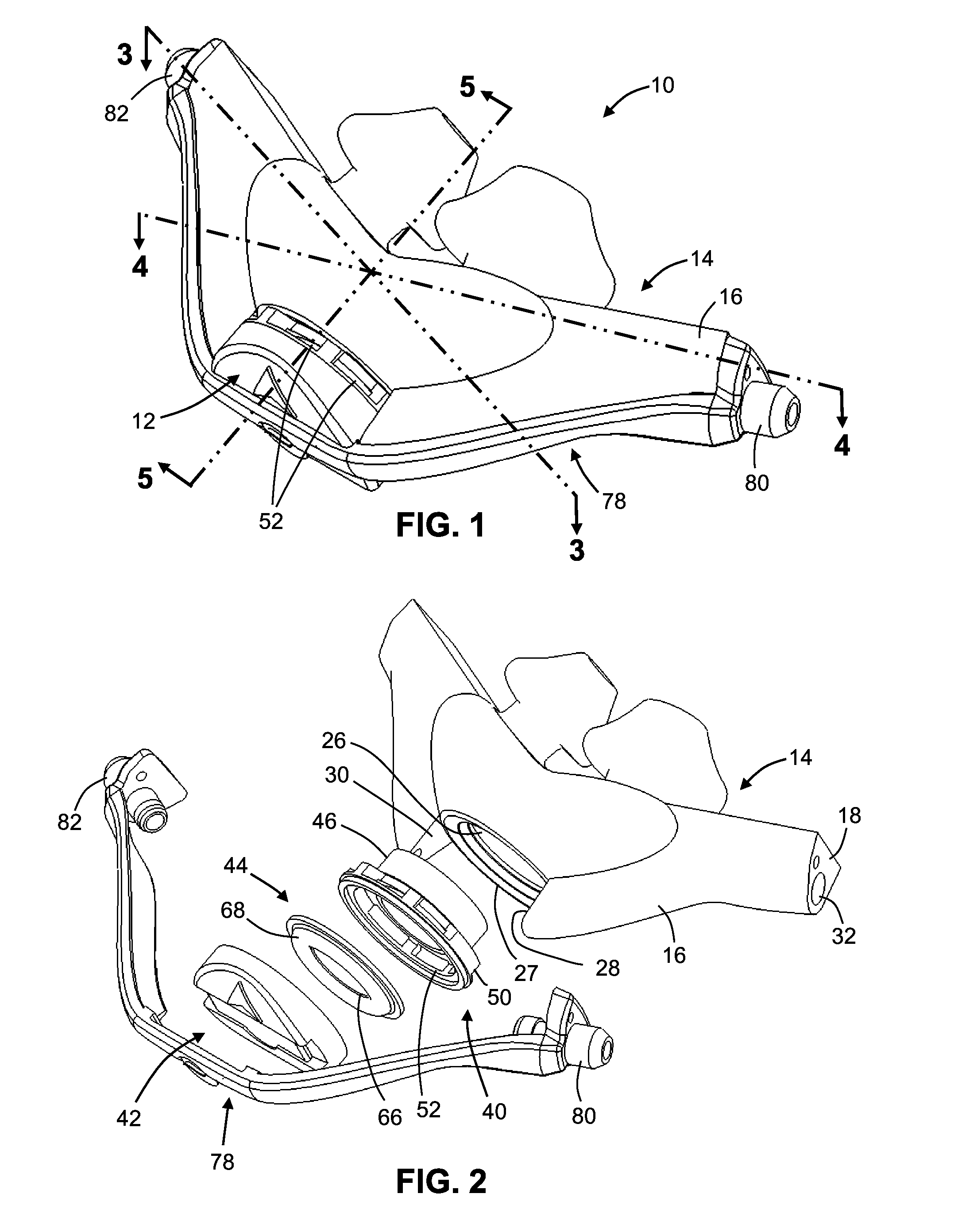
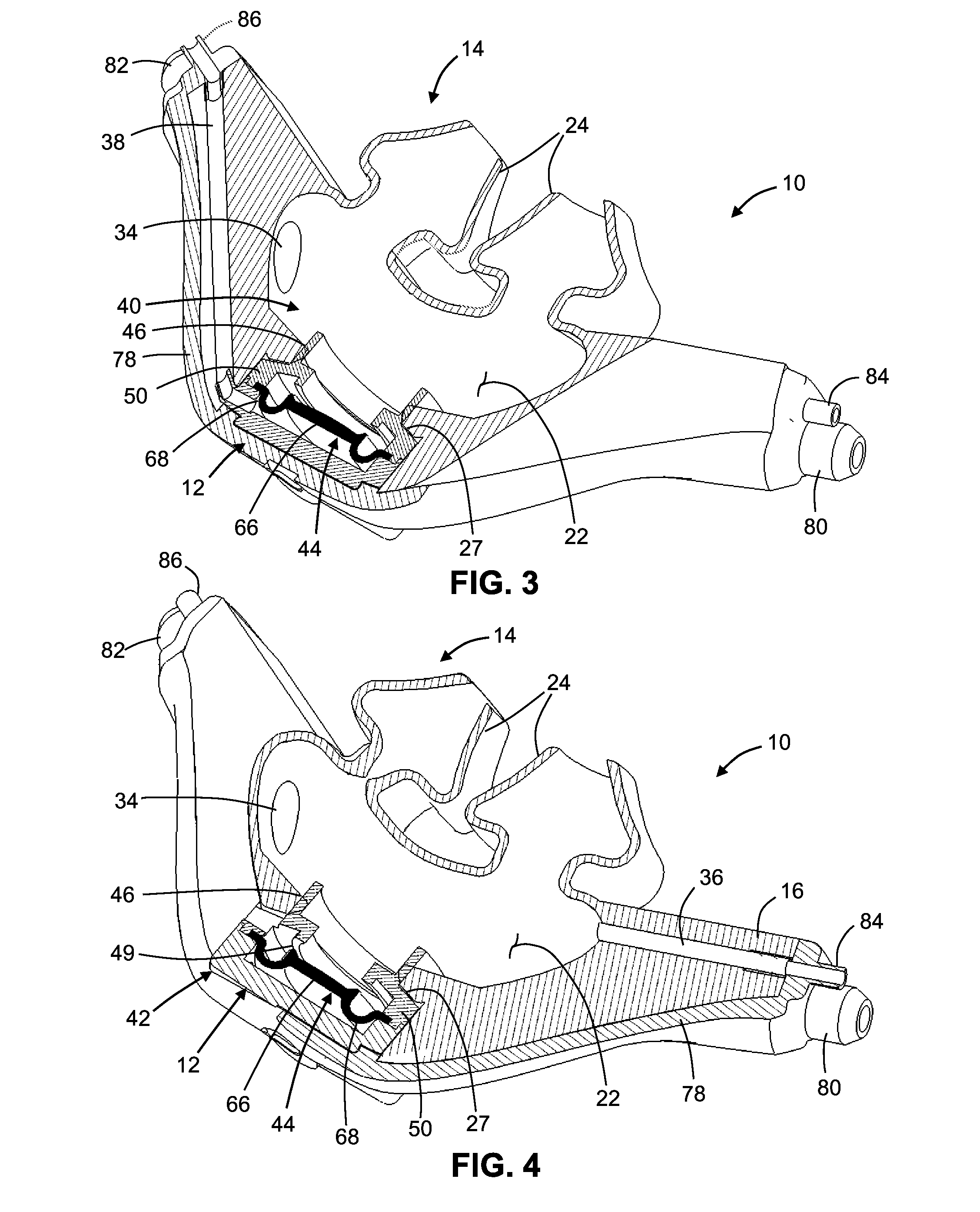
[0048]Referring now to the drawings wherein the showings are for purposes of illustrating various embodiments of the present invention only, and not for purposes of limiting the same, FIGS. 1-4 depict a ventilation mask 10 (e.g., a nasal pillows mask) constructed in accordance with the present invention. Though the mask 10 is depicted as a nasal pillows mask, those skilled in the art will recognize that other ventilation masks are contemplated herein, such as nasal prongs masks, nasal masks, fill face masks and oronasal masks. As such, for purposes of this application, the term mask and / or ventilation mask is intended to encompass all such mask structures. The mask 10 includes an integrated, diaphragm-implemented, piloted exhalation valve 12, the structural and functional attributes of which will be described in more detail below.

[0049]As shown in FIGS. 1-5, the mask 10 comprises a housing or cushion 14. The cushion 14, which is preferably fabricated from a silicone elastomer having...


PUM


Abstract

In accordance with the present invention, there is provided a mask for achieving positive pressure mechanical ventilation (inclusive of CPAP, ventilator support, critical care ventilation, emergency applications), and a method for a operating a ventilation system including such mask. The mask of the present invention includes a piloted exhalation valve that is used to achieve the target pressures / flows to the patient. The pilot for the valve may be pneumatic and driven from the gas supply tubing from the ventilator. The pilot may also be a preset pressure derived in the mask, a separate pneumatic line from the ventilator, or an electro-mechanical control. The mask of the present invention may further include a heat and moisture exchanger (HME) which is integrated therein.

Description

CROSS-REFERENCE TO RELATED APPLICATIONS[0001]The present application is a continuation-in-part of U.S. application Ser. No. 13 / 411,348 entitled VENTILATION MASK WITH INTEGRATED PILOTED EXHALATION VALVE filed Mar. 2, 2012, which claims priority to U.S. Provisional Patent Application Ser. No. 61 / 499,950 entitled VENTILATION MASK WITH INTEGRATED PILOTED EXHALATION VALVE filed Jun. 22, 2011, and U.S. Provisional Patent Application Ser. No. 61 / 512,750 entitled VENTILATION MASK WITH INTEGRATED PILOTED EXHALATION VALVE AND METHOD OF VENTILATING A PATIENT USING THE SAME filed Jul. 28, 2011, the disclosures of which are incorporated herein by reference.STATEMENT RE: FEDERALLY SPONSORED RESEARCH / DEVELOPMENT[0002]Not ApplicableBACKGROUND OF THE INVENTION[0003]1. Field of the Invention[0004]The present invention relates to systems and methods for controlling delivery of a pressurized flow of breathable gas to a patient and, more particularly, to a ventilation mask such as a full face mask, nasa...

Claims


Application Information

Patent Timeline
Patent Type & Authority Applications(United States)
IPC IPC(8): A61M16/06A61M16/00A61B5/03A61B5/00A61B5/097A61M16/20A61B5/087
CPCA61M16/0875A61M16/1045A61M16/0666A61M16/20A61M16/0066A61M16/207A61B5/4836A61B5/097A61B5/03A61M16/0833A61M16/201A61B5/087A61M16/0858A61M16/0605A61M16/0003A61M16/0622A61M16/208A61M2016/0027A61M2205/3334
Inventor BRAMBILLA, ENRICO
Owner BREATHE TECHNOLOGIES INC
Why Eureka
Try Eureka