Surgical clip

a technology of surgical clip and clip, applied in the field of surgical clip, can solve the problems of resiliently flexible elements undergoing plastic deformation, risk of clip opening too far, application forceps being accidentally interchanged, etc., and achieve the effect of not impairing the function of stop elements

Active Publication Date: 2013-07-18
AESCULAP AG
View PDF8 Cites 14 Cited by
  • Summary
  • Abstract
  • Description
  • Claims
  • Application Information

AI Technical Summary

Benefits of technology

[0017]In a variant of simpler design, a prism structure of negative configuration can receive and sufficiently centre the already existing, outward-curved structure of the second end of the other clip arm. Further, the prism structure need not necessarily have its outermost region formed by a sharp prism edge. Rather, the outermost region can also be shaped in a flattened or rounded configuration without impairing the function of the stop element.
[0018]In a more preferred embodiment, the complementary-configured stop elements are configured such that axial guiding of

Problems solved by technology

With the clips of different closing force requiring differently configured clip application forceps, there is the danger of the application forceps being accidentally interchanged, with the risk of a clip being opened too

Method used


Image

  • Surgical clip
  • Surgical clip
  • Surgical clip

Examples


Embodiment Construction

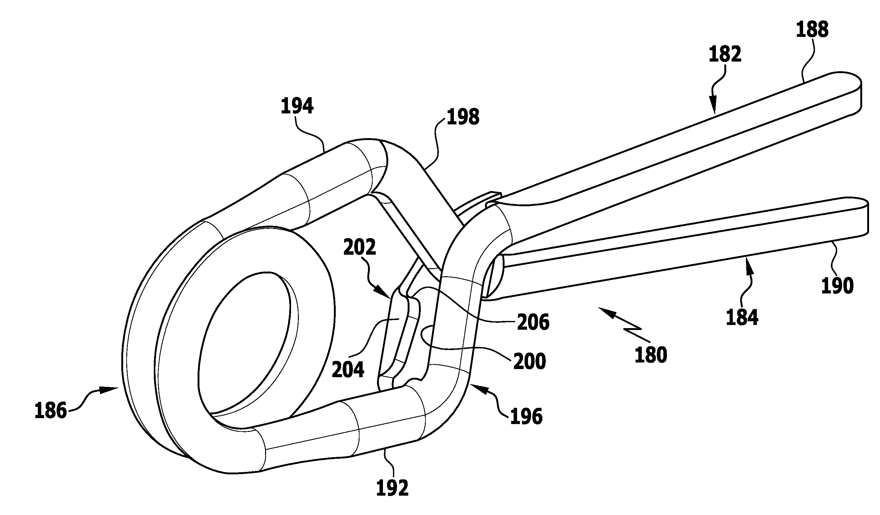
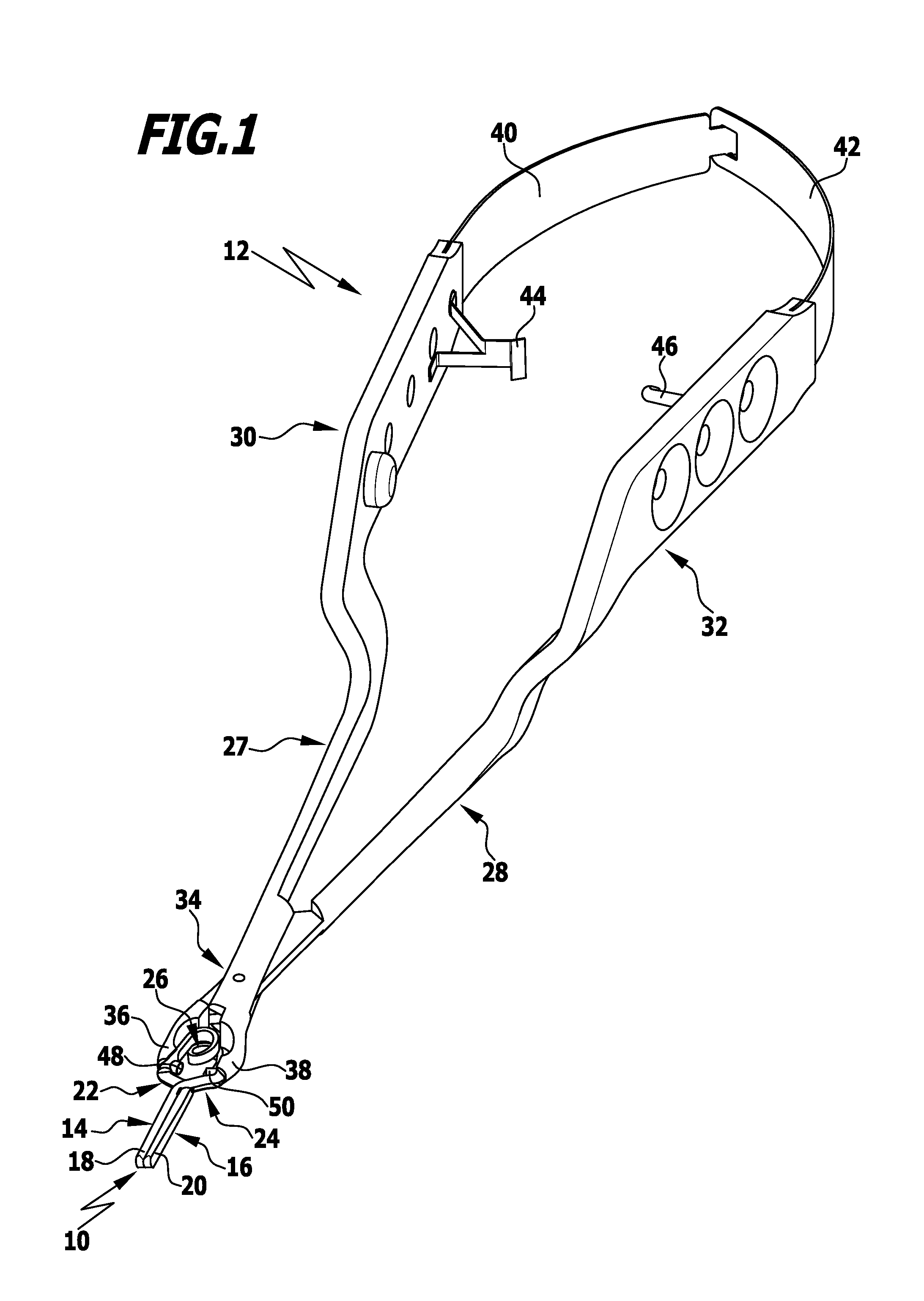
[0041]FIG. 1 shows a surgical clip 10 constructed in accordance with the invention, with the surgical clip being held in a clip application forceps 12.

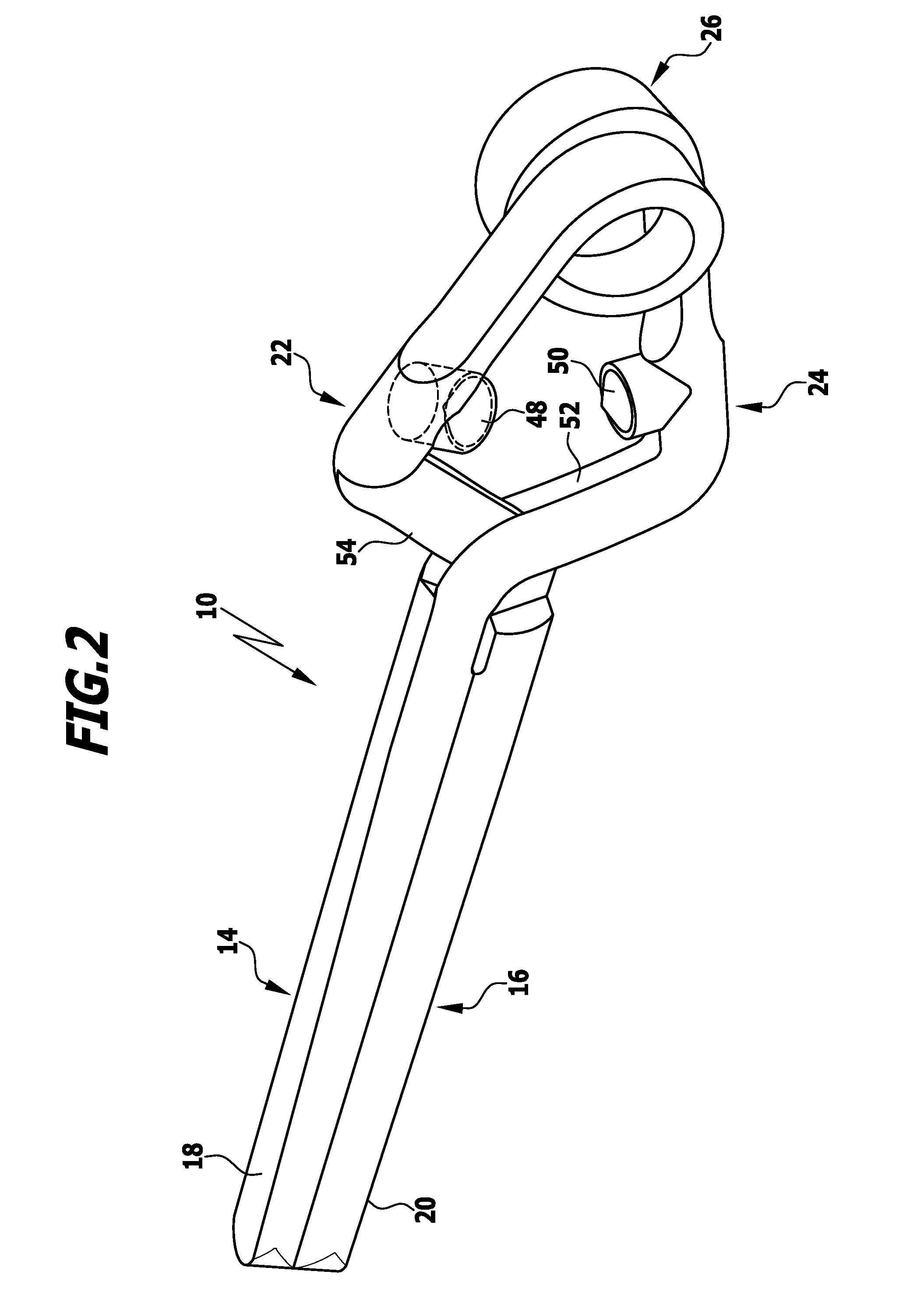
[0042]The surgical clip 10 constructed in accordance with the invention, which will be described in greater detail in conjunction with FIG. 2, comprises two clip arms 14, 16, the first free ends 18, 20 of which are in surface contact with each other when the clip is in closed condition, i.e., in its rest position, as shown in FIG. 1.

[0043]The two clip arms 14, 16 are configured to cross each other and their second ends 22, 24 opposite the first free ends 18, 20 are connected to each other via a spring element 26.

[0044]The clip application forceps 12 has two handle arms 27, 28 which are adjoined by two handle parts 30, 32. The handle arms 27, 28 are articulately interconnected at their front region 34.

[0045]The jaw parts 36, 38 of the forceps 12, which adjoin the handle arms 27, 28 beyond the articulation 34, are formed with concave st...


PUM


Abstract

A surgical clip is provided having two clip arms and a resiliently flexible element via which the two clip arms are connected to each other. The two clip arms each have a first free end, these first free ends being held parallel to and in contact with each other with a predetermined closing force by the resiliently flexible element when the clip is in a rest position. The clip arms are held at a second end opposite the free end on the resiliently flexible element. The clip arms have between their first and second ends sections configured to cross each other. The clip arms further have stop elements configured to complement each other. The stop elements are adapted to be brought in mutual contact when the clip is transferred from the rest position to an application position in which the free ends are spaced apart from each other.

Description

[0001]This application is a continuation of international application number PCT / EP2011 / 064923 filed on Aug. 30, 2011 and claims the benefit of German application number 10 2010 037 468.7 filed on Sep. 10, 2010, which are incorporated herein by reference in their entirety and for all purposes.BACKGROUND OF THE INVENTION[0002]The invention relates to a surgical clip, in particular for use as an implant, wherein use as an aneurysm clip has outstanding importance here.[0003]Surgical clips are known that have two clip arms and a resiliently flexible element which connects the two clip arms to each other at one of their ends.[0004]The two clip arms each have a first free end, these first free ends being held parallel to and in contact with each other with a predetermined closing force by the resiliently flexible element when the clip is in a rest position, and a second end opposite the free end, these second ends being held on the resiliently flexible element.[0005]Between their first, f...

Claims


Application Information

Patent Timeline
IPC IPC(8): A61B17/122
CPCA61B17/1227A61B17/128A61B2019/304A61B2017/305A61B17/2833A61B2090/034A61B2034/302
Inventor WEISSHAUPT, DIETERNESPER, MARKUSSTEINHILPER, KLAUS-DIETERPLEIL, THOMAS
Owner AESCULAP AG
Why Eureka
Try Eureka