System and method for inspecting railroad ties

a technology of inspection system and grading method, which is applied in the direction of distance measurement, mechanical measurement arrangement, instruments, etc., can solve the problems of cross-ties deterioration, time-consuming visual inspection process in practice, inspection and grading system and method have a variety of limitations in their us

Active Publication Date: 2013-07-25
LORAM TECH INC
View PDF8 Cites 75 Cited by
  • Summary
  • Abstract
  • Description
  • Claims
  • Application Information

AI Technical Summary

Benefits of technology

[0009]It has been recognized that it would be advantageous to develop a fully computerized system and method for inspecting railroad tracks, which can both identify and locate railroad ties, tie plates, and appurtenant structures, and also determine condition metrics of the these.

Problems solved by technology

Over time, environmental factors can cause the crossties to deteriorate until they must be replaced.
The process of visual inspection is quite time consuming In practice, inspection of the track is performed by an inspector walking along the track to inspect and record the conditions of the crossties and / or fasteners, which are spaced approximately every 20-inches along the track.
However, some prior railroad tie inspection and grading systems and methods have a variety of limitations in their use and present a variety concerns.

Method used


Image

  • System and method for inspecting railroad ties
  • System and method for inspecting railroad ties
  • System and method for inspecting railroad ties

Examples


Embodiment Construction

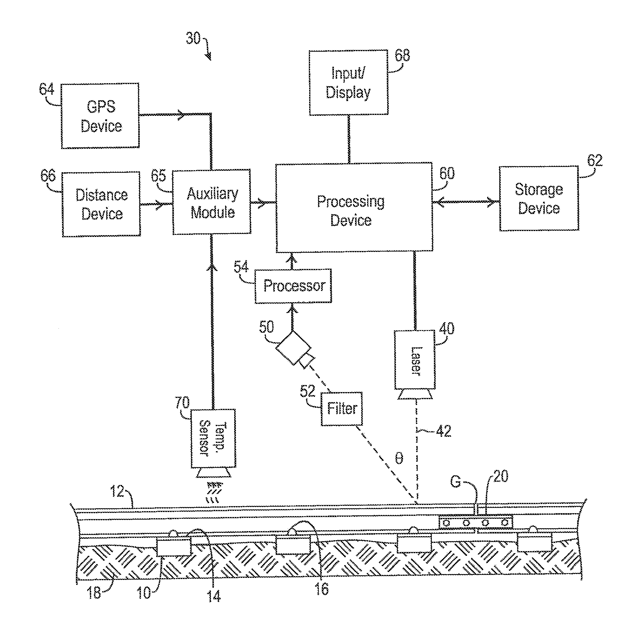
[0034]Reference will now be made to exemplary embodiments illustrated in the drawings, and specific language will be used herein to describe the same. It will nevertheless be understood that no limitation of the scope of the invention is thereby intended. Alterations and further modifications of the inventive features illustrated herein, and additional applications of the principles of the inventions as illustrated herein, which would occur to one skilled in the relevant art and having possession of this disclosure, are to be considered within the scope of the invention.

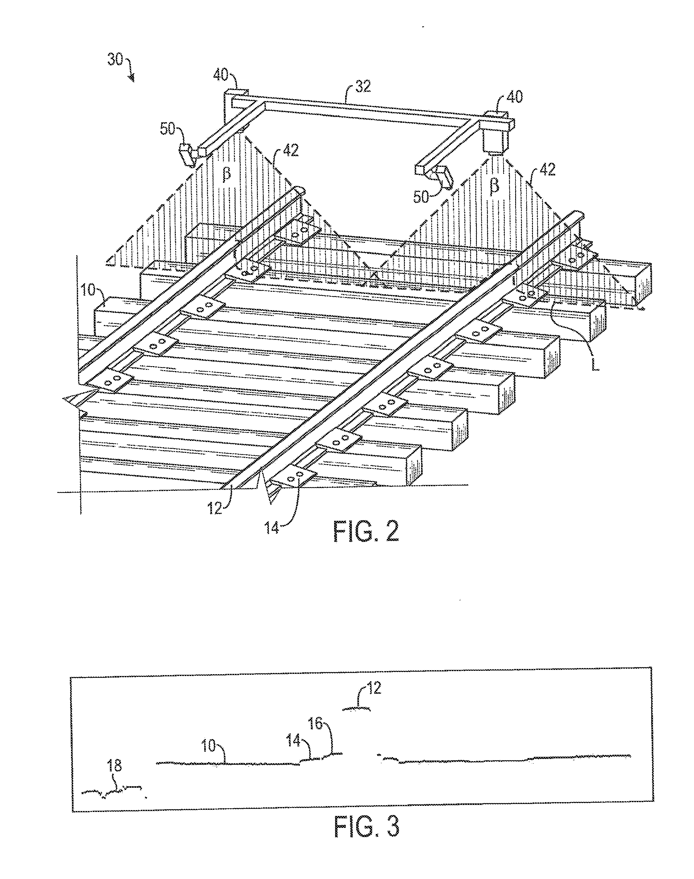
[0035]Referring to FIGS. 1 and 2, an exemplary embodiment of a system 30 for inspecting railroad track according to certain teachings of the present disclosure is illustrated. In FIG. 1, the disclosed inspection system 30 is schematically illustrated relative to a railroad track. In FIG. 2, a portion of the disclosed inspection system 30 is illustrated in a perspective view relative to railroad track.

[0036]As best sh...


PUM


Abstract

A system for inspecting railroad ties in a railroad track includes a light generator, an optical receiver and a processor. The light generator is oriented to project a beam of light across the railroad track while moving along the railroad track in a travel direction. The optical receiver is oriented to receive at least a portion of the beam of light reflected from the railroad track and configured to generate image data representative of a profile of at least a portion of the railroad track. The processor is configured to analyze the image data by applying one or more algorithms configured to find boundaries of a railroad tie and determine one or more condition metrics associated with the railroad tie.

Description

PRIORITY CLAIM[0001]This application is a continuation-in-part of U.S. application Ser. No. 12 / 465,473, entitled “SYSTEM AND METHOD FOR INSPECTING SURFACES USING OPTICAL WAVELENGTH FILTERING,” filed May 13, 2009, which is a continuation-in-part of U.S. application Ser. No. 11 / 172,618, entitled, “SYSTEM AND METHOD FOR INSPECTING RAILROAD TRACK, filed Jun. 30, 2005, which is a non-provisional application claiming benefit of U.S. Provisional Application Ser. No. 60 / 584,769, also entitled, “SYSTEM AND METHOD FOR INSPECTING RAILROAD TRACK, filed Jun. 30, 2004, each being hereby incorporated by reference in their entirety.BACKGROUND[0002]1. Field of the Invention[0003]The present invention relates generally to systems and methods for inspecting surfaces and, more particularly to systems and methods for inspection and grading of wood railroad ties.[0004]2. Related Art[0005]Railroads are generally constructed on a base layer of compacted, crushed stone material. A layer of gravel ballast re...

Claims


Application Information

Patent Timeline
Patent Type & Authority Applications(United States)
IPC IPC(8): G01B11/24
CPCB61K9/08G01B11/24G01C3/08B61L23/044B61L23/045B61K9/00G01M99/00
Inventor KAINER, JOHN J.AARON, CHARLES W.GRISSOM, GREGORY T.MAURICIO, ANTONIO R.BELCHER, JEB E.PAGLIUCO, DAVID M.WAMANI, WILSON T.NAGEL, II, JOHN A.VILLAR, CHRISTOPHER M.ORREL, STEVEN C.BERTILSON, ZECHARIAH
Owner LORAM TECH INC
Why Eureka
Try Eureka