Commissioning devices for automation systems

a technology for automation systems and commissioning devices, applied in the field of automation systems, can solve the problems of limiting the mass deployment of home automation, the complexity of the commissioning process, and the inability of components to work together, and achieve the effect of reducing the assistance of users

Active Publication Date: 2013-07-25
ZONOFF
View PDF16 Cites 199 Cited by
  • Summary
  • Abstract
  • Description
  • Claims
  • Application Information

AI Technical Summary

Benefits of technology

[0023]The user interface presented by the software application will vary based on the platform being used, but the underlining purpose will be the same in most cases. The user is assisted in setup of home automation devices by referencing the database and communicating with the device via the appropriate home automation standard. The device will also function to minimize assistance from the user.
[0024]Whenever possible, settings will be done to other devices in the local network or home automation network without having to interact with the end user.

Problems solved by technology

In some cases, these components are not even designed to work together, and glue logic is required to commission them into an interoperable system.
Because of the wide variety of setup possibilities, the interfaces for the commissioning process are so complex that a trained installer or a sophisticated end-user are generally the only ones able to perform these installations.
This complexity of these systems, interfaces, and configuration procedures, along with the cost of a trained installer has held home automation back from mass deployment.
Some suppliers have attempted to simplify the commissioning process, but the resulting process has not been made simple enough.
Other suppliers sell pre-configured systems, but the resulting systems are less useful and are difficult to expand.
Certain usage patterns may also trigger a user to be prompted with questions whose answers may result in changes to the setup of the devices in their home.

Method used


Image

  • Commissioning devices for automation systems
  • Commissioning devices for automation systems
  • Commissioning devices for automation systems

Examples


Embodiment Construction

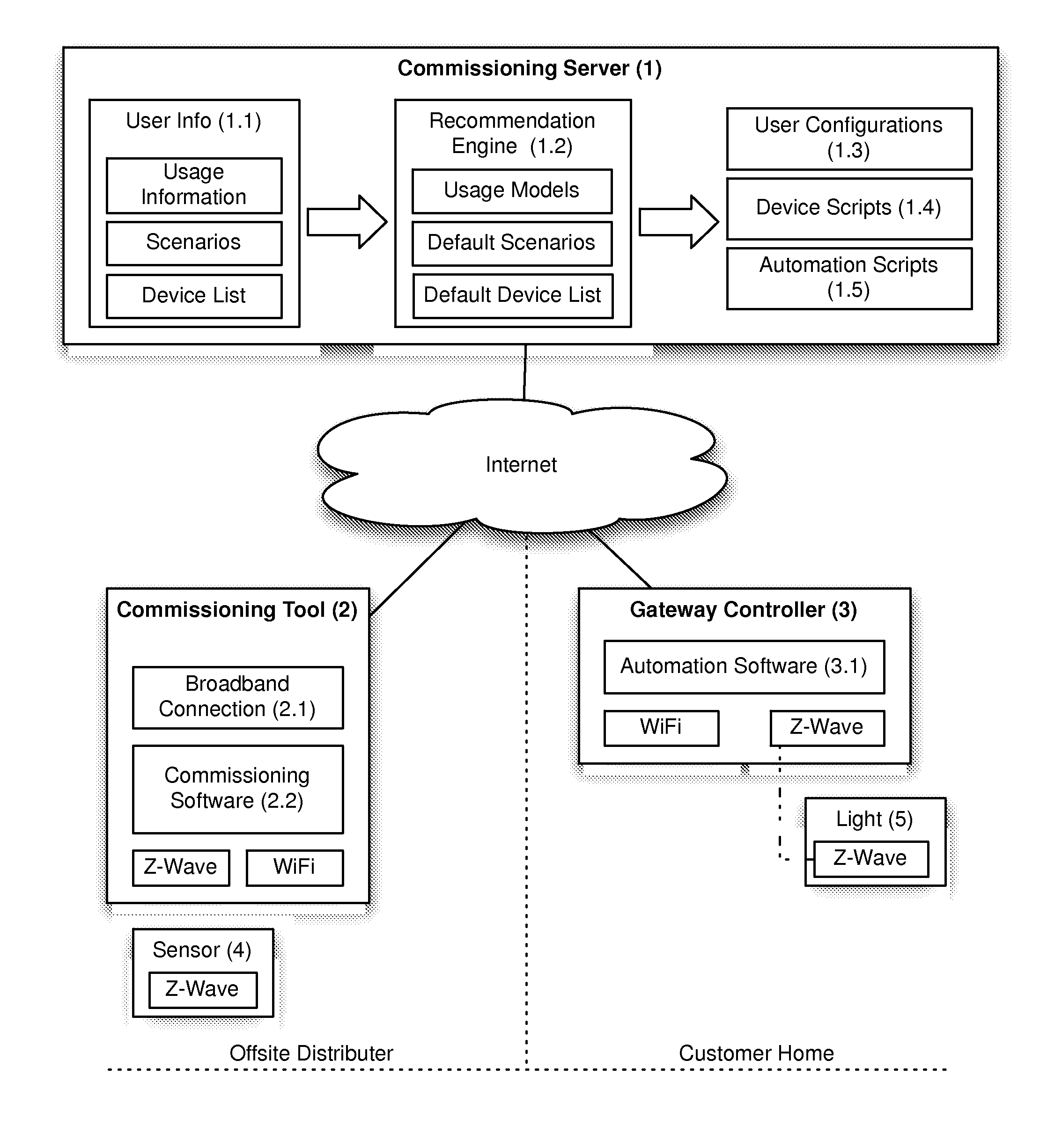
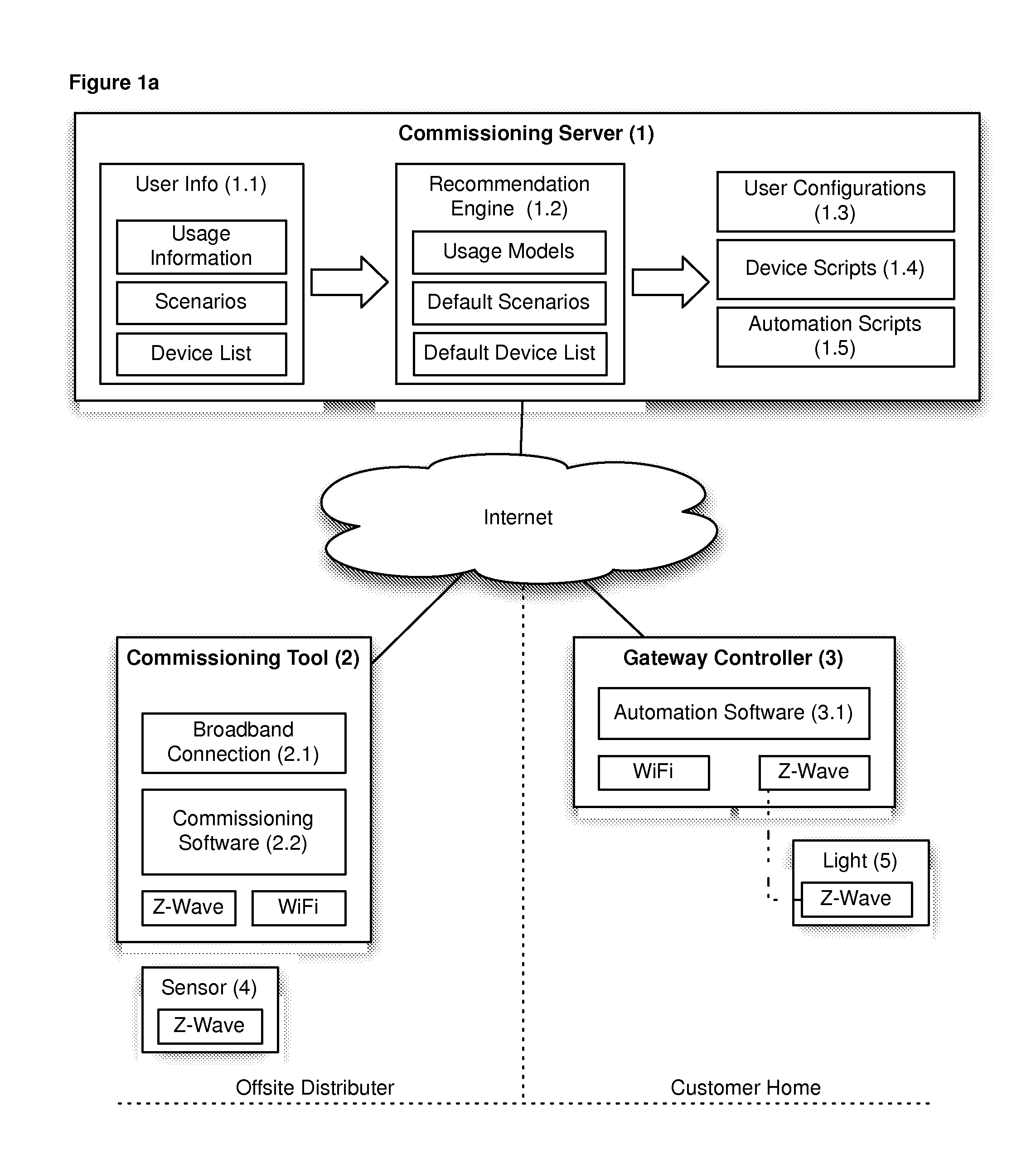
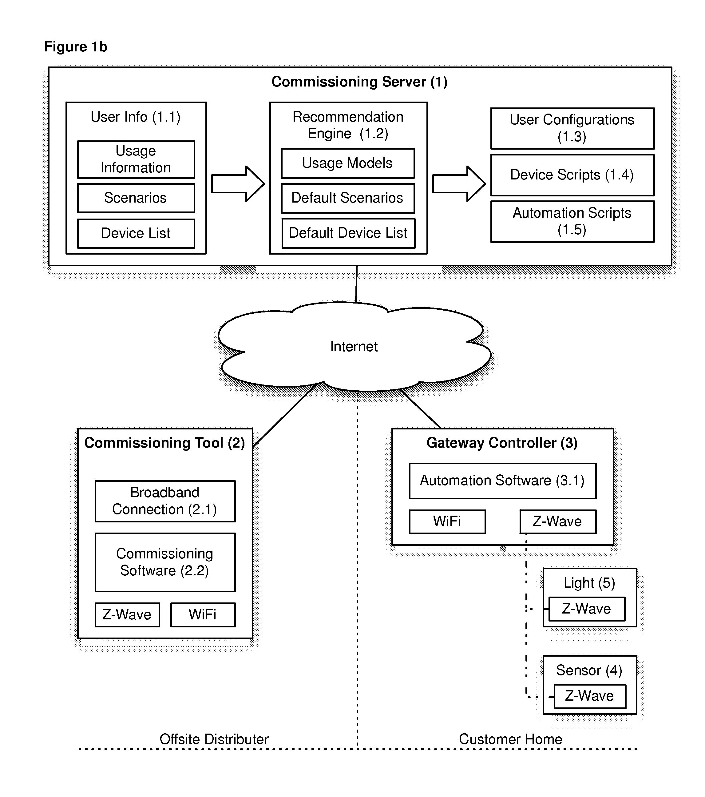
[0033]FIG. 1a and FIG. 1b are block diagrams representing, on the lower left, an Offsite Distributer and, on the lower right, a Customer Home. Gateway Controller (3) is connected to the Internet using WiFi and uses a wireless standard such as Z-Wave to communicate with and control Light (5). Gateway (3) contains Automation Software (3.1) to operate connected devices in the home. In FIG. 1a, there is an operating Z-Wave ecosystem that contains Light (5) in the customer's home.

[0034]FIG. 1a and FIG. 1b depict connectivity through the Internet to a Commissioning Server (1) for setup and control of connected devices. The Commissioning Server (1) offers a scenario to the homeowner where a new sensor (4) will enable light (5) to turn on and off when occupancy is detected in the home. The Commissioning Server (1) selected the aforementioned scenario to present to the user by using the User Info (1.1) about what devices are installed in the Customer House, usage of those devices, and a list...


PUM


Abstract

Remote commissioning for an automation system enables a retailer to sell a new device to a customer pre-configured to work together with devices that are already a part of the user's automation system. Knowledge of how the devices are likely to be used at the automation system's location, a list of existing devices already installed and how they are configured, possible input from the customer, and the end user's current usage patterns are optionally used to configure the devices before they leave the store. Assisted local commissioning for an automation device enables an end user to commission devices themselves by simplifying the installation and commissioning process. The system uses a reference database of devices that includes information on how to commission the devices along with user-manual information and pictures for physical installation, and setup instructions so the system can walk a user through the process step by step.

Description

CROSS-REFERENCE TO RELATED APPLICATIONS[0001]This application claims the benefit of the filing date of U.S. provisional application Nos. 61 / 632,337 and 61 / 632,338, both of which were filed on Jan. 23, 2012, the teachings of both of which are incorporated herein by reference in their entirety.BACKGROUND[0002]1. Field of the Invention[0003]The present invention relates to automation systems. More particularly but not exclusively, the invention relates to techniques for commissioning devices for automation systems for homes, businesses, campuses, buildings, and the like.[0004]2. Description of the Related Art[0005]This section introduces concepts that may help facilitate a better understanding of the invention. Accordingly, the statements of this section are to be read in that light and are not to be understood as admissions about what is prior art or what is not prior art. In the following, the term “home automation” may be used in descriptions of the prior art and embodiments of the ...

Claims


Application Information

Patent Timeline
Patent Type & Authority Applications(United States)
IPC IPC(8): H04L12/24
CPCH04L12/2807H04L41/0806
Inventor BALOG, MICHAELHARRIS, MICHAELBUCHERT, RYAN
Owner ZONOFF
Why Eureka
Try Eureka