
Tool Holder Having Set Screw for Clamping a Cutting Insert Therein

a tool holder and screw technology, applied in the field of tool holders, can solve the problems of limiting the depth of insertion weakening the structure and limiting the operational range of the tool holder

Active Publication Date: 2013-08-08
ISCAR LTD
View PDF1 Cites 27 Cited by
  • Summary
  • Abstract
  • Description
  • Claims
  • Application Information

AI Technical Summary

Benefits of technology

The present invention provides a tool holder with improved clamping capabilities for holding cutting inserts. The tool holder has a base jaw and a clamping jaw with a slot for holding the insert. A force application member, such as a set screw, is retained in a bore and engages with the slot for securely holding the insert. The method for clamping the cutting insert involves positioning it in the holder, sliding it into the slot, and rotating the set screw to apply a clamping force between the support surface and the insert surface. The cutting tool also includes the tool holder and the cutting insert actively clamped in the holder. The technical effects of this invention include improved holding power of cutting inserts and easy and secure mounting of inserts in tool holders.

Problems solved by technology

The depth of insertion of the tool holder is limited by the amount of force that can be efficiently transmitted from the tightening of the bolt to the clamping of the cutting insert.
The threaded hole in the plate under the slot may inherently weaken the structure of tool holder and limit its operational range.

Method used


Image

  • Tool Holder Having Set Screw for Clamping a Cutting Insert Therein
  • Tool Holder Having Set Screw for Clamping a Cutting Insert Therein
  • Tool Holder Having Set Screw for Clamping a Cutting Insert Therein

Examples


Embodiment Construction

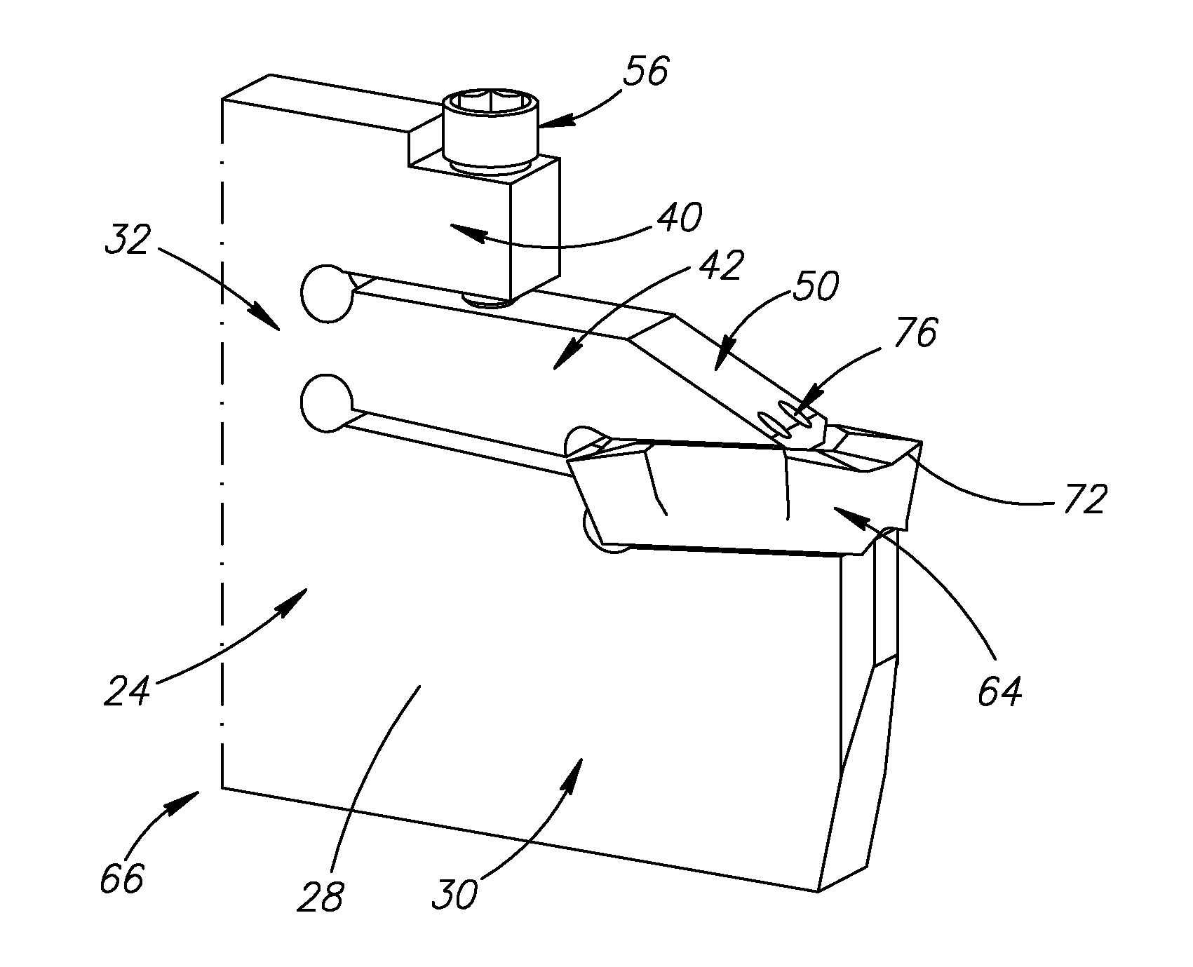
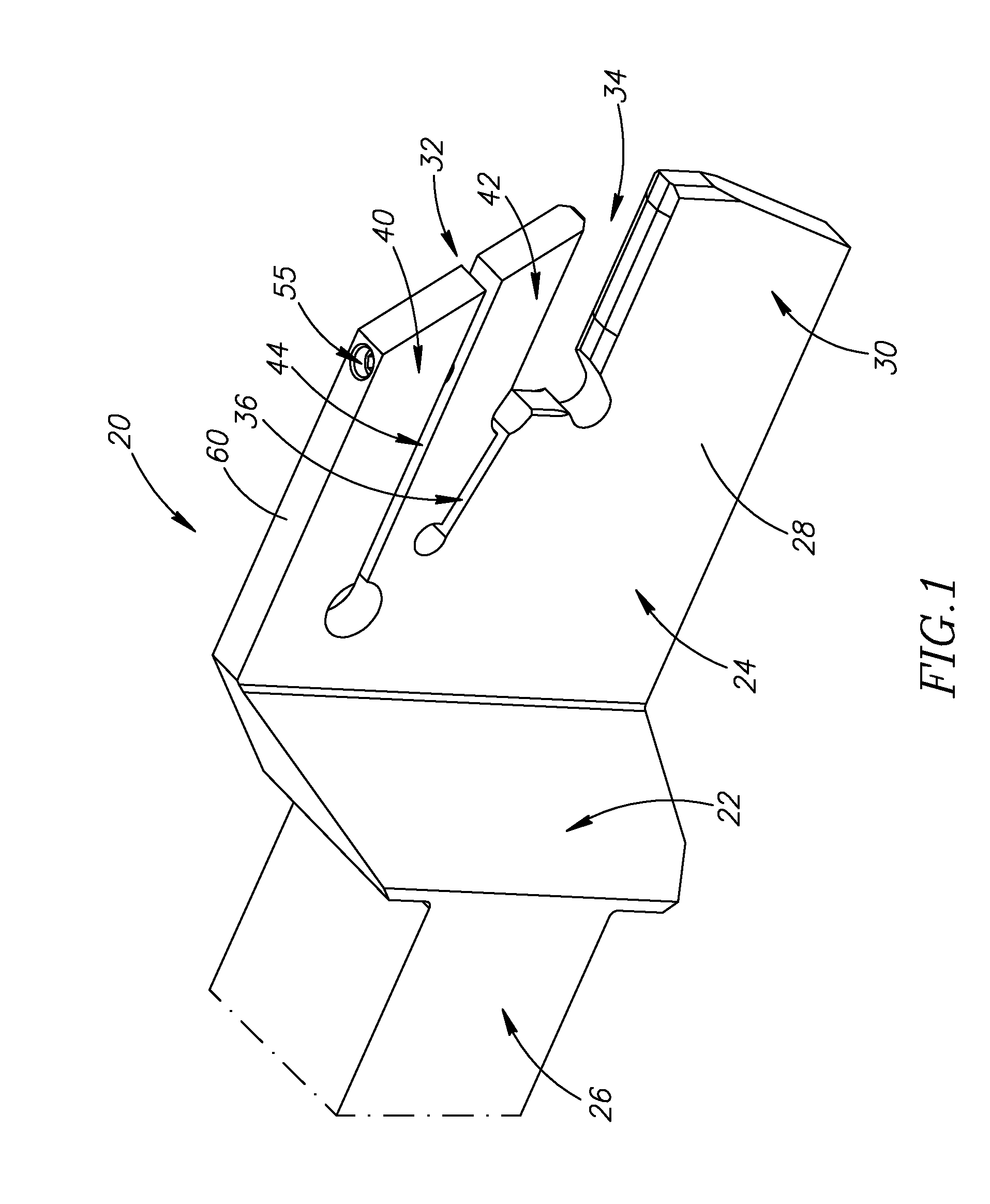
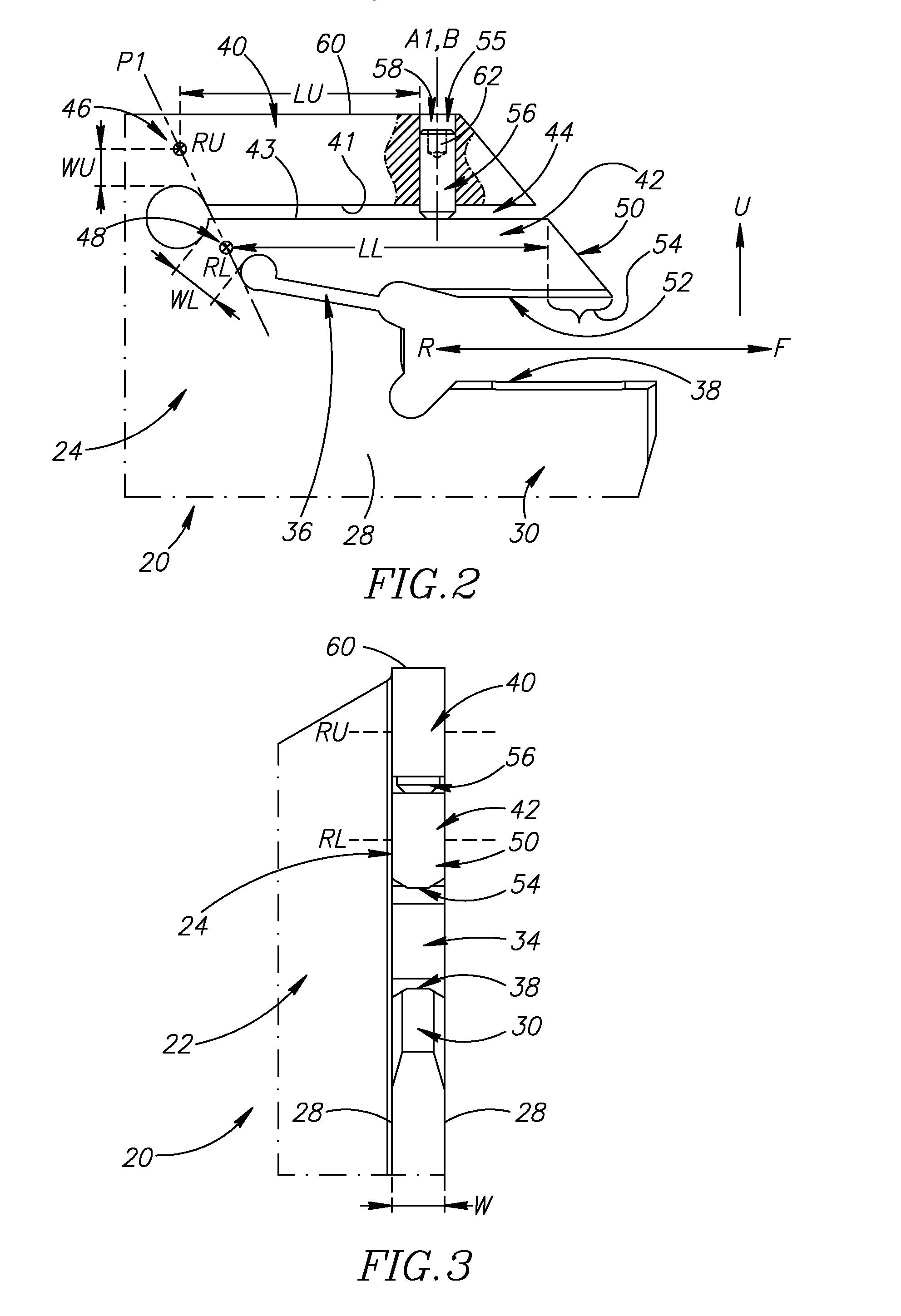
[0032]Attention is first drawn to FIGS. 1, 2 and 3, showing a tool holder 20 in accordance with some embodiments of the present invention. The tool holder 20, which may be manufactured from hardened steel, comprises a body portion 22 and a holding portion 24.

[0033]In some embodiments of the present invention, as shown in FIG. 1, the body portion 22 may be rigidly fixed to the holding portion 24 and include a shank 26 extending away from the holding portion 24.

[0034]Also, in some embodiments of the present invention, as shown in FIG. 3, the holding portion 24 may be blade shaped having a generally constant holder width w between opposing side surfaces 28.

[0035]The holding portion 24 has a base jaw 30 and a clamping jaw 32, with an insert receiving pocket 34 therebetween extending in a forward to rearward direction F, R, and a first slot 36 extending generally rearwardly from the insert receiving pocket 34.

[0036]In some embodiments of the present invention, as shown in FIGS. 1 and 2, ...


PUM

PropertyMeasurementUnit
Forceaaaaaaaaaa
Widthaaaaaaaaaa
Resilienceaaaaaaaaaa

Abstract

A tool holder has a body portion and a holding portion, the holding portion having a base jaw and a clamping jaw, with an insert receiving pocket therebetween extending in a forward to rearward direction, and a first slot extending generally rearwardly from the insert receiving pocket. The base jaw has a support surface, and the clamping jaw has upper and lower arms separated by a second slot and extending in the generally forward direction. The lower arm has a forward end and an under surface facing towards the support surface, the under surface having a clamping portion adjacent the forward end. The upper arm has a bore which opens out to the second slot at a location rearward of the clamping portion. The bore can accommodate a force application member which can contact and displace the lower arm towards the base jaw to clamp a cutting insert.

Description

RELATED APPLICATIONS[0001]This application claims priority to U.S. Provisional Patent Application No. 61 / 594,038, filed 2 Feb. 2012, whose contents are incorporated by reference in their entirety.FIELD OF THE INVENTION[0002]The present invention relates to a tool holder for use in metal cutting processes in general, and for grooving and parting operations in particular.BACKGROUND OF THE INVENTION[0003]Within the field of tool holders used in grooving and parting operations, there are many examples of cutting inserts being clamped in an insert receiving pocket of a narrow blade-shaped holding portion between a rigid base jaw and a flexible clamping jaw. Some of these tool holders are configured such that the cutting insert is actively clamped between the clamping jaw and the base jaw by means of a clamping member.[0004]U.S. Pat. No. 3,894,322 discloses such a tool holder having a rectangular shank and a head at the forward end thereof. The front side of the head is in the form of a n...

Claims


Application Information

Patent Timeline
IPC IPC(8): B23B27/16B23B29/12
CPCB23B27/10B23B29/043B23B2205/02Y10T407/227Y10T407/2282Y10T407/2286Y10T29/49826
Inventor HECHT
Owner ISCAR LTD
Features
  • Generate Ideas
  • Intellectual Property
  • Life Sciences
  • Materials
  • Tech Scout
  • Unparalleled Data Quality
  • Higher Quality Content
  • 60% Fewer Hallucinations
Learn More