Image heating apparatus

a heating apparatus and image technology, applied in the field of image heating apparatus, can solve the problems of microscopically scratching the rotational heating member, microscopically scratching, and reducing thereby the rotational buffing member in performance, and achieve the effect of preventing the scratching

Active Publication Date: 2013-08-15
CANON KK
View PDF15 Cites 33 Cited by
  • Summary
  • Abstract
  • Description
  • Claims
  • Application Information

AI Technical Summary

Benefits of technology

[0006]The present invention makes the toner on the rotational heating member of an image heating device (apparatus) transfer onto the nip forming member of the image heating device before the rotational heating member is buffed by the rotational buffing member. Therefore, it can prevent the toner on the rotational heating member from transferring onto the rotational buffing member.

Problems solved by technology

Thus, it is possible that when they are conveyed through the nip of an image heating apparatus (device), they will microscopically scratch the rotational heating member of the image heating device, with the burrs which their edges have.
Therefore, it is possible that they will be microscopically scratched by the burrs.
However, these methods are problematic in that it is possible that when the rotational heating member is buffed by the rotational buffing member, the toner particles on the rotational heating member will transfer onto the rotational buffing member, and fill up the microscopic recesses in the peripheral surface of the rotational buffing member, reducing thereby the rotational buffing member in performance.

Method used


Image

  • Image heating apparatus
  • Image heating apparatus
  • Image heating apparatus

Examples


embodiment 1

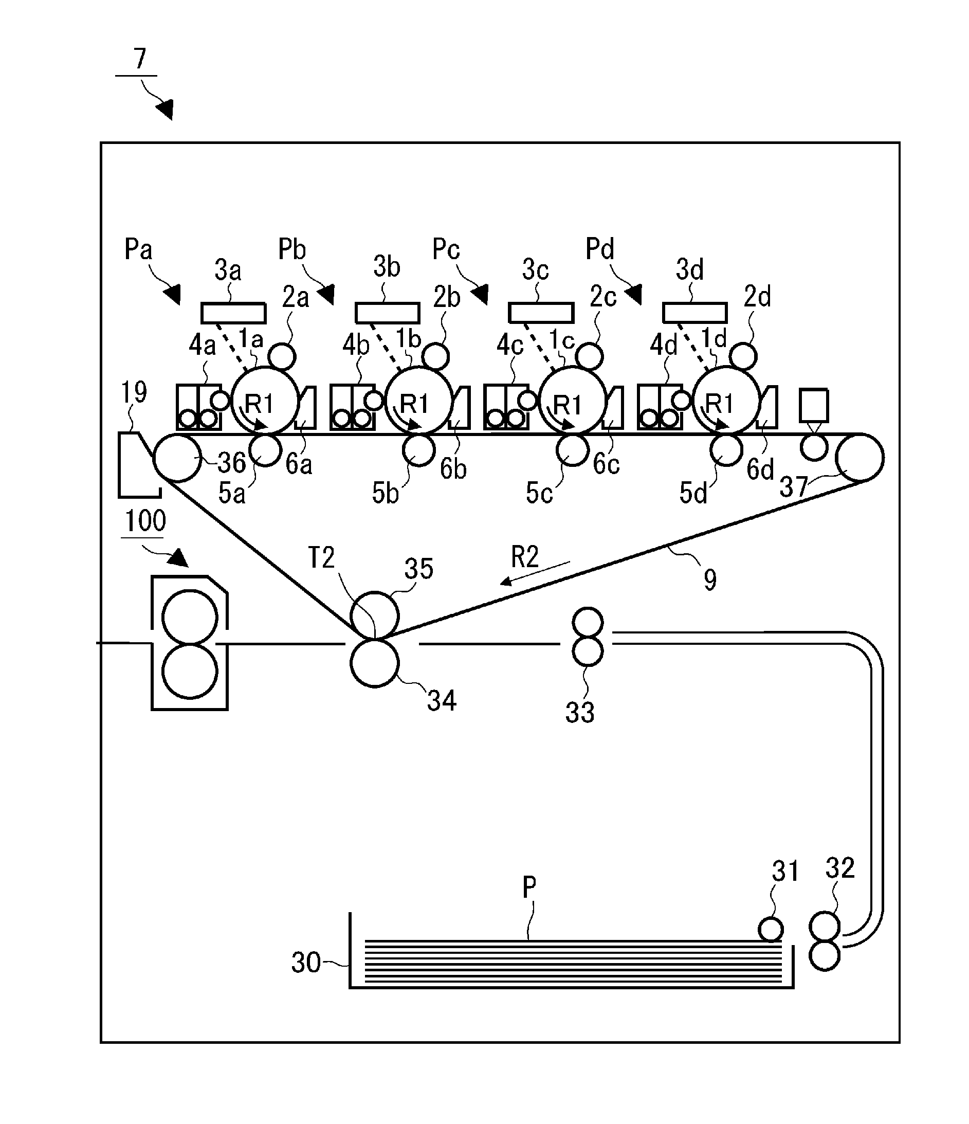
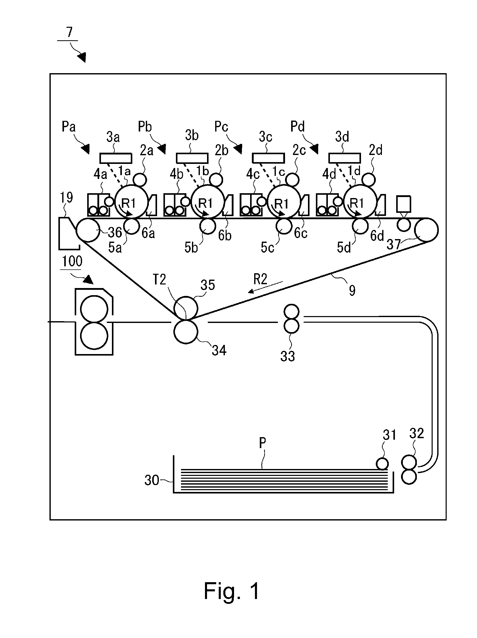
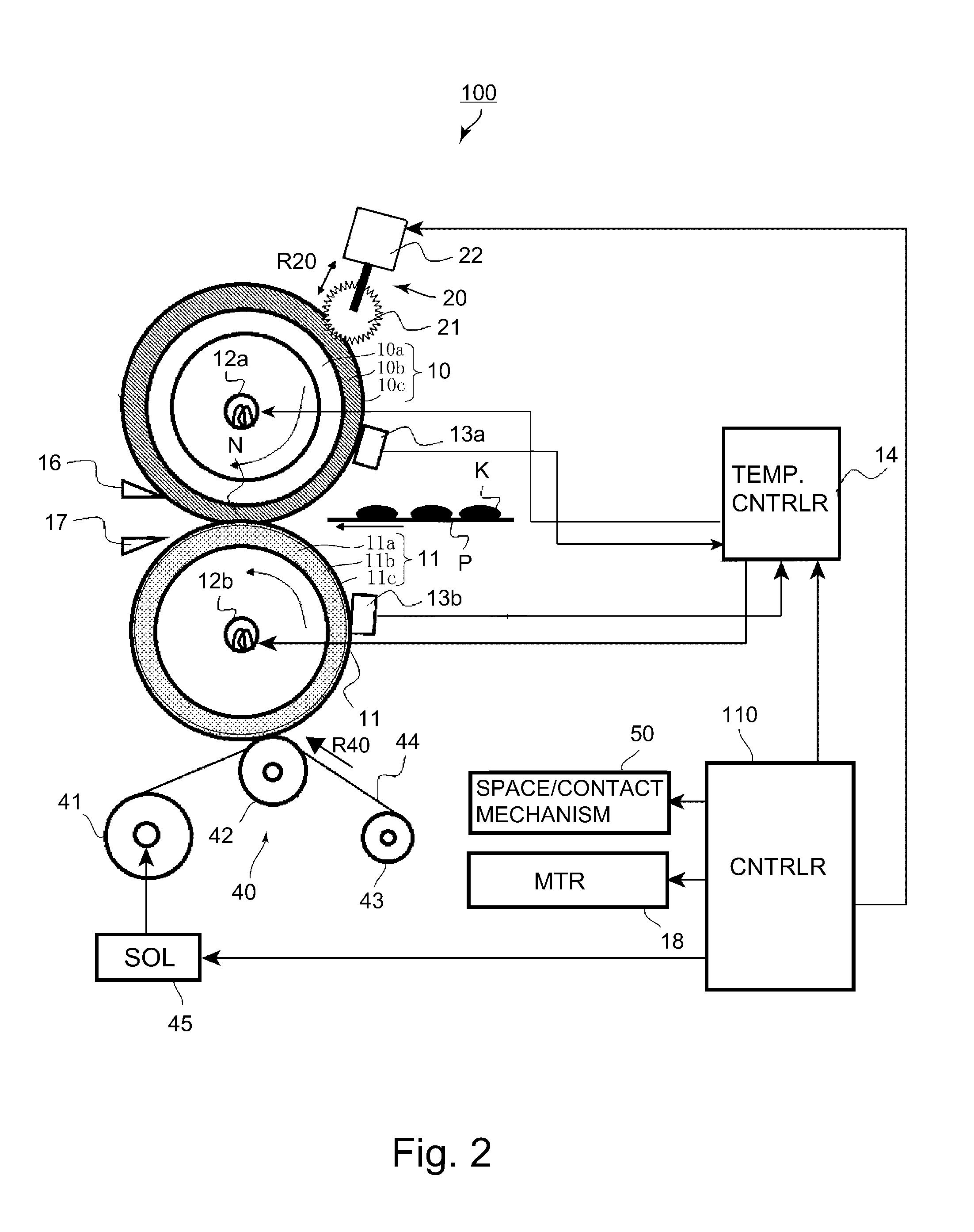
[0056]FIG. 4 is a flowchart of the control sequence, in the first embodiment of the present invention, for the operation for buffing the peripheral surface of the fixation roller 10 with the buffing roller 21. In the first embodiment, the offset toner on the fixation roller 10, that is, the toner having transferred onto the peripheral surface of the fixation roller 10 from a sheet of recording medium, on which unfixed toner image was present, is recovered by the web-type cleaning device 40 by way of the pressure roller 11, immediately before the fixing device 100 begins to be operated in the buffing mode (cleaning mode).

[0057]Referring to FIG. 2, the fixation roller 10, which is an example of a rotational heating member, heats the image bearing surface of a sheet of recording medium. The pressure roller 11, which is an example of a pressure applying rotational member, is positioned so that it can be placed in contact with (pressed upon) the fixation roller 10 to form a nip for heati...

embodiment 2

[0077]FIG. 5 is a flowchart of the control sequence, in the second embodiment, for the operation for buffing the pressure roller. In the second embodiment, the amount of the offset toner having adhered to the peripheral surface of the fixation roller 10 is estimated. Then, the length of time the fixing device 100 is to be operated in the cleaning mode is set in proportion to the estimated amount of the offset toner on the peripheral surface of the fixation roller 10. In cleaning mode, the greater a sheet of recording medium is in basis weight, and / or the lower the ambient temperature, the longer the length of time the fixation roller 10 is to be operated in the cleaning mode is set.

[0078]Referring to FIG. 2, in this embodiment, the control section 110 is provided with not only the above described cumulative sheet counter for cumulatively counting the number of sheets of recording medium processed by the fixing device 100, but also, an offset toner amount counter which is for estimat...

embodiment 3

[0090]In the second embodiment, the length of time the fixing device 100 is operated in the cleaning mode is adjusted according to the estimated amount of the offset toner on the fixation roller 10. In comparison, in the third embodiment, the frequency with which the fixing device 100 is put in the cleaning mode is adjusted according to the estimated amount of the offset toner on the fixation roller 10. That is, the greater in basis weight the sheet of recording medium, and / or lower the ambient temperature, the higher the frequency with the fixing device 100 is operated in the cleaning mode.

[0091]Each time a sheet of recording medium is processed by the fixing device 100, the control section 110 adds a preset value to the value in the offset toner amount counter. Then, as the value in the offset toner amount counter reaches 1,200, it operates the fixing device 100 in the cleaning mode, and then, in the buffing mode, that is, the mode in which the buffing roller 21 is used. However, ...


PUM

PropertyMeasurementUnit
thicknessaaaaaaaaaa
thicknessaaaaaaaaaa
thicknessaaaaaaaaaa

Abstract

An image heating apparatus includes a image heating roller in a nip; a nip forming member; a heating roller rubbing roller; a moving mechanism for moving the rubbing roller between a spaced position and a rubbing position; and a controller for executing operations in first and second modes. In the first mode, the heating roller is rotated with the rubbing roller in the spaced position and the heating roller in contact with the nip forming member with a target temperature of the heating roller higher than that of the nip forming member. In the second mode, the rubbing roller is contacted with the heating roller rubbing the surface of the heating roller. The temperature difference in the first mode between the target temperature of the heating roller and that of the nip forming member is larger than the temperature difference when the toner image is heated by the nip.

Description

FIELD OF THE INVENTION AND RELATED ART[0001]The present invention relates to an image heating apparatus which has a rotational heating member and a nip forming member and heats a toner image on recording medium, in the nip between the rotational heating member and nip forming member. In particular, it relates to an image heating apparatus having a member for buffing the rotational heating member, in addition to the rotational heating member and nip forming member. An image heating apparatus is employed by an electrophotographic image forming apparatus such as a copying machine, a printer, a facsimile machine, a multifunction image forming apparatus capable of functioning as two or more of the preceding machines and apparatuses, etc.[0002]It is a common practice in the field of an electrophotographic image forming apparatus to subject a toner image formed on recording medium to heat and pressure in the nip between the rotational heating member and nip forming member of an image heati...

Claims


Application Information

Patent Timeline
Patent Type & Authority Applications(United States)
IPC IPC(8): H05B1/00
CPCH05B1/00H05B1/0241G03G15/2025G03G15/2039H05B3/0095G03G15/2064
Inventor TANAKA, MASANOBUKITAGAWA, OKITAKADA, SHIGEAKISHINAGAWA, AKIYOSHIKAWAI, HIROKI
Owner CANON KK
Why Eureka
Try Eureka