Multicast optical switch

optical switch technology, applied in optics, instruments, optical light guides, etc., can solve the problems of large waveguide crossover number, loss, complexity, etc., and achieve the effect of increasing the number of inputs and outputs of a multi-channel optical switch, limiting the amount of crosstalk, and reducing the complexity

Active Publication Date: 2013-08-15
LUMENTUM OPERATIONS LLC
View PDF3 Cites 14 Cited by
  • Summary
  • Abstract
  • Description
  • Claims
  • Application Information

AI Technical Summary

Benefits of technology

[0007]The present invention uses optical beams freely propagating in a bulk optical medium, such as vacuum, air, glass, etc., to make optical crossovers required in a multicast optical switch. Freely propagating optical beams can cross each other without introducing mutual optical loss. The amount of crosstalk is limited by scattering in the optical medium, which can be made very low. Therefore, the number of the crossover connections, and consequently the number of inputs and outputs of a multicast optical switch, can be greatly increased. A diffractive bulk optical element can be used to provide optical beam splitting. Diffractive bulk optic beam splitters for splitting a multi-wavelength optical beam into two, four, eight, and sixteen beams of similar optical power are presently commercially available. Another important advantage of a bulk optic diffractive beamsplitter is that a single bulk beamsplitter can be used to split multiple input optical beams.

Problems solved by technology

One drawback of the multicast optical switch 100 is complexity.
However, one challenge with the PLC implementation is the large number of waveguide crossovers involved.
Each waveguide crossing adds loss and creates a possibility for unwanted crosstalk.

Method used


Image

  • Multicast optical switch
  • Multicast optical switch
  • Multicast optical switch

Examples


Embodiment Construction

[0042]While the present teachings are described in conjunction with various embodiments and examples, it is not intended that the present teachings be limited to such embodiments. On the contrary, the present teachings encompass various alternatives, modifications and equivalents, as will be appreciated by those of skill in the art.

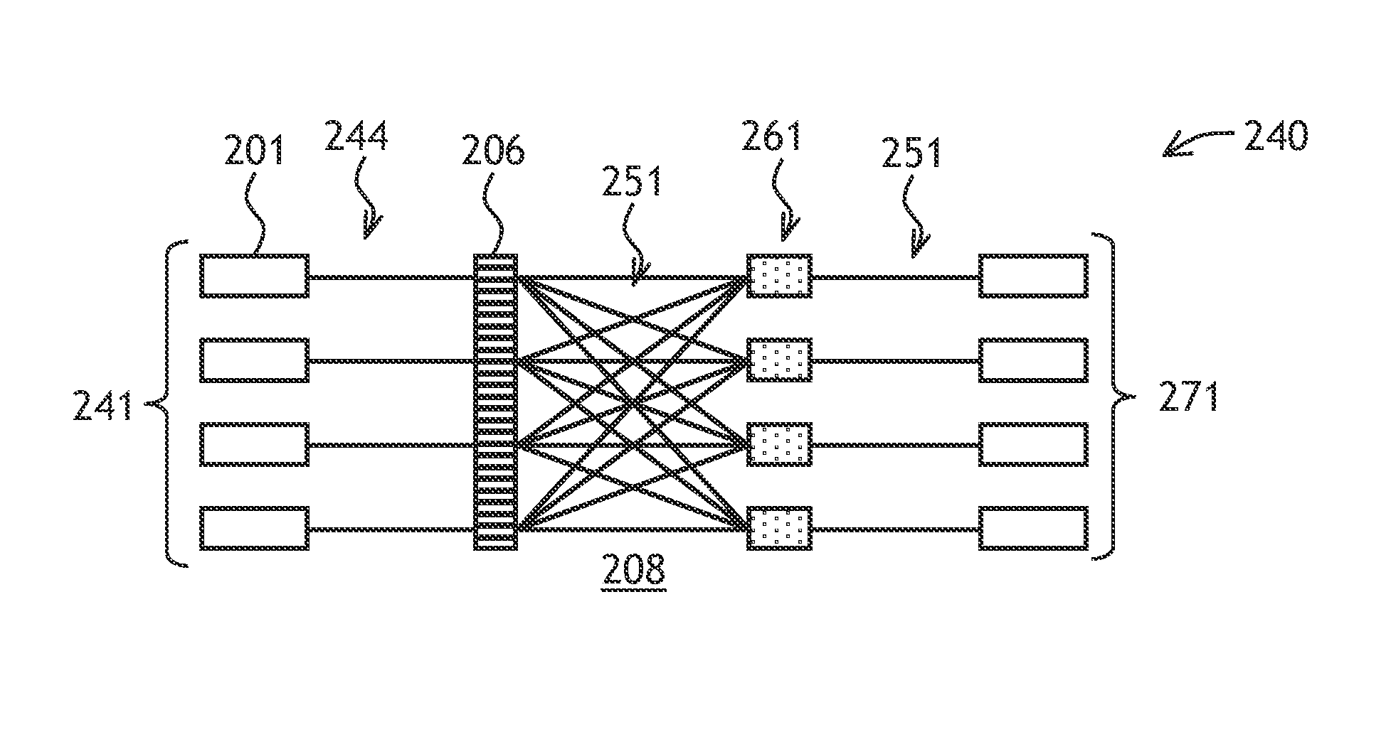
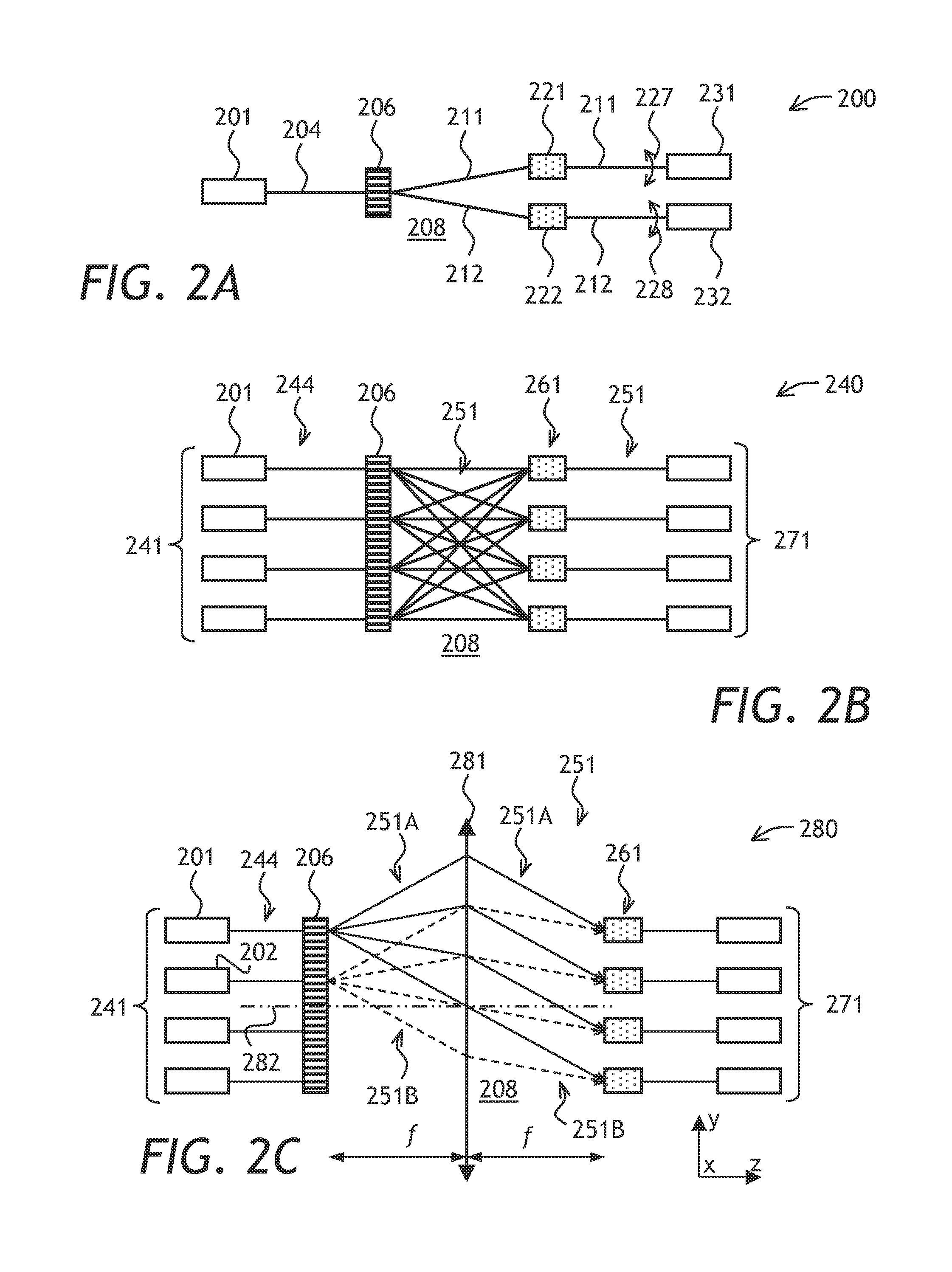
[0043]Referring to FIG. 2A, a multicast optical switch 200 of the invention includes a first input port 201 for receiving a first optical beam 204, which includes a plurality of wavelength channels, a diffractive bulk optical element 206 coupled to the first input port 201, for splitting the first optical beam 204 impinging on the diffractive bulk optical element 206 into first and second portions 211 and 212, respectively, which propagate in a bulk optical medium 208. Each of the first and second portions 211 and 212 includes a portion of each of the plurality of wavelength channels. First and second directors 221 and 222, respectively, receive the first...


PUM


Abstract

A multicast optical switch uses a diffractive bulk optical element, which splits at least one input optical beam into sub-beams, which freely propagate in a medium towards an array of directors, such as MEMS switches, for directing the sub-beams to output ports. Freely propagating optical beams can cross each other without introducing mutual optical loss. The amount of crosstalk is limited by scattering in the optical medium, which can be made virtually non-existent. Therefore, the number of the crossover connections, and consequently the number of inputs and outputs of a multicast optical switch, can be increased substantially without a loss or a crosstalk penalty.

Description

CROSS-REFERENCE TO RELATED APPLICATIONS[0001]The present invention claims priority from U.S. Provisional Patent Application No. 61 / 512,459 filed Jul. 28, 2011 which is incorporated herein by reference for all purposes.TECHNICAL FIELD[0002]The present invention relates to optical switching, and in particular to multicast optical switching in fiberoptic networks.BACKGROUND OF THE INVENTION[0003]In an optical communications network, an optical signal is modulated with digital information and transmitted over a length of optical fiber from a source location to a destination location. An optical cross-connect module allows switching of optical signals from one optical fiber to another. A multicasting optical switch allows one to switch optical signals from one optical fiber to not one but, simultaneously, to a plurality of optical fibers, or to switch optical signals from a plurality of input optical fibers to a plurality of output optical fibers, such that optical signals in any of the ...

Claims


Application Information

Patent Timeline
Patent Type & Authority Applications(United States)
IPC IPC(8): G02B27/42G02B6/35
CPCG02B27/106G02B27/1093G02B6/3518G02B6/3556G02B6/3546B81B7/04G02B6/3512G02B27/42G02B6/3534G02B26/0833G02B27/1086
Inventor MCLAUGHLIN, SHELDONROORDA, PETER DAVIDCOLBOURNE, PAULKEYWORTH, BARRIE
Owner LUMENTUM OPERATIONS LLC
Why Eureka
Try Eureka