Reinforced nonwoven fabric

a non-woven fabric and reinforced technology, applied in the field of reinforced non-woven fabrics, can solve the problems of no special requirements for weight reduction and mechanical stability in such applications, and the known instructions are inadequate for the manufacture of components subject to more stringent requirements

Inactive Publication Date: 2013-08-15
SGL AUTOMOTIVE CARBON FIBERS
View PDF6 Cites 1 Cited by
  • Summary
  • Abstract
  • Description
  • Claims
  • Application Information

AI Technical Summary

Benefits of technology

[0022]Another aspect of the present invention is a component that encompasses the flat textile structure according to the invention or the article according to the invention impregnated with a polymer matrix.

Problems solved by technology

During the manufacture of flat textile structures with a relatively low cohesion among the textile fibers, for example in the case of nonwoven or pile, the simplest handling processes can pose a problem, such as rolling the flat structures on and off, and automatically feeding them to additional production stages.
However, no special requirements on weight reduction and mechanical stability are necessary in such applications.
For this reason, the known instructions are inadequate for the manufacture of components subject to more stringent requirements in this regard, for example in the automotive or aviation industries.
One difficultly posed by carbon fibers in terms of manufacturing technique has to do with the composition of the carbon fiber surface.
As a consequence, carbon fibers in flat textile structures exhibit a very weak adhesion between the fibers, and hence lead to a low cohesion between the flat textile structures.
This low adhesion or low cohesion finally impacts the manufacturing process for flat textile structures comprised of carbon fibers, thus necessitating a reinforcing grid.
However, primarily the nonwoven layers are responsible for the mechanical stability of the final component that integrates the flat textile structure owing to their percentage of carbon fibers, so that the presence of a reinforcing grid has a detrimental effect on the strength-weight ratio for the component.
The draping ability here deteriorates as the strength of the reinforcing grid rises.

Method used


Image

  • Reinforced nonwoven fabric
  • Reinforced nonwoven fabric
  • Reinforced nonwoven fabric

Examples


Embodiment Construction

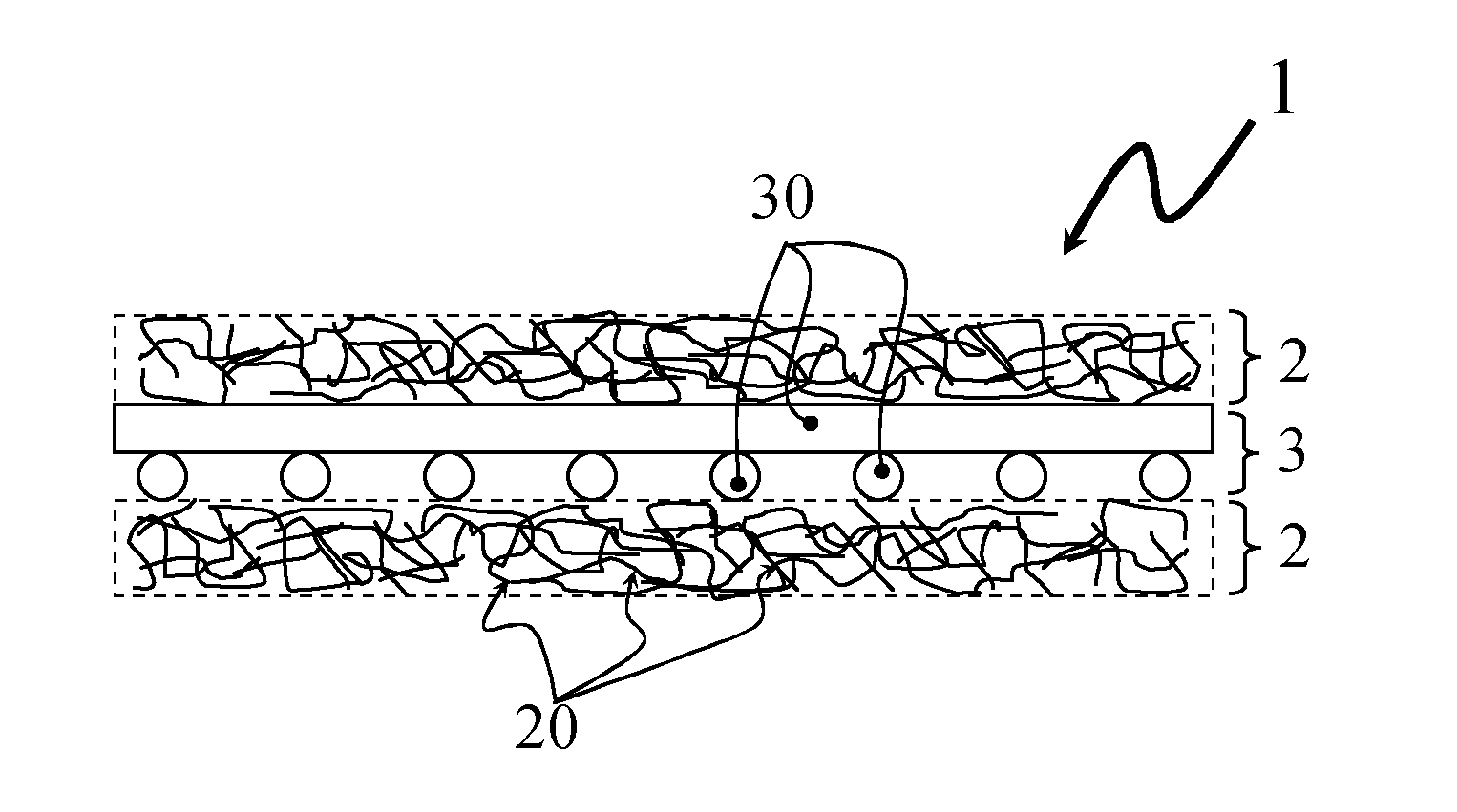
[0024]FIG. 1 shows the schematic structural design of a flat textile structure (1) according to one aspect of the present invention. The reinforcing grid (3) according to the invention, as represented by its grid braces (30), is here secured between two pile layers (2) according to the invention, as represented by its fibers (20).

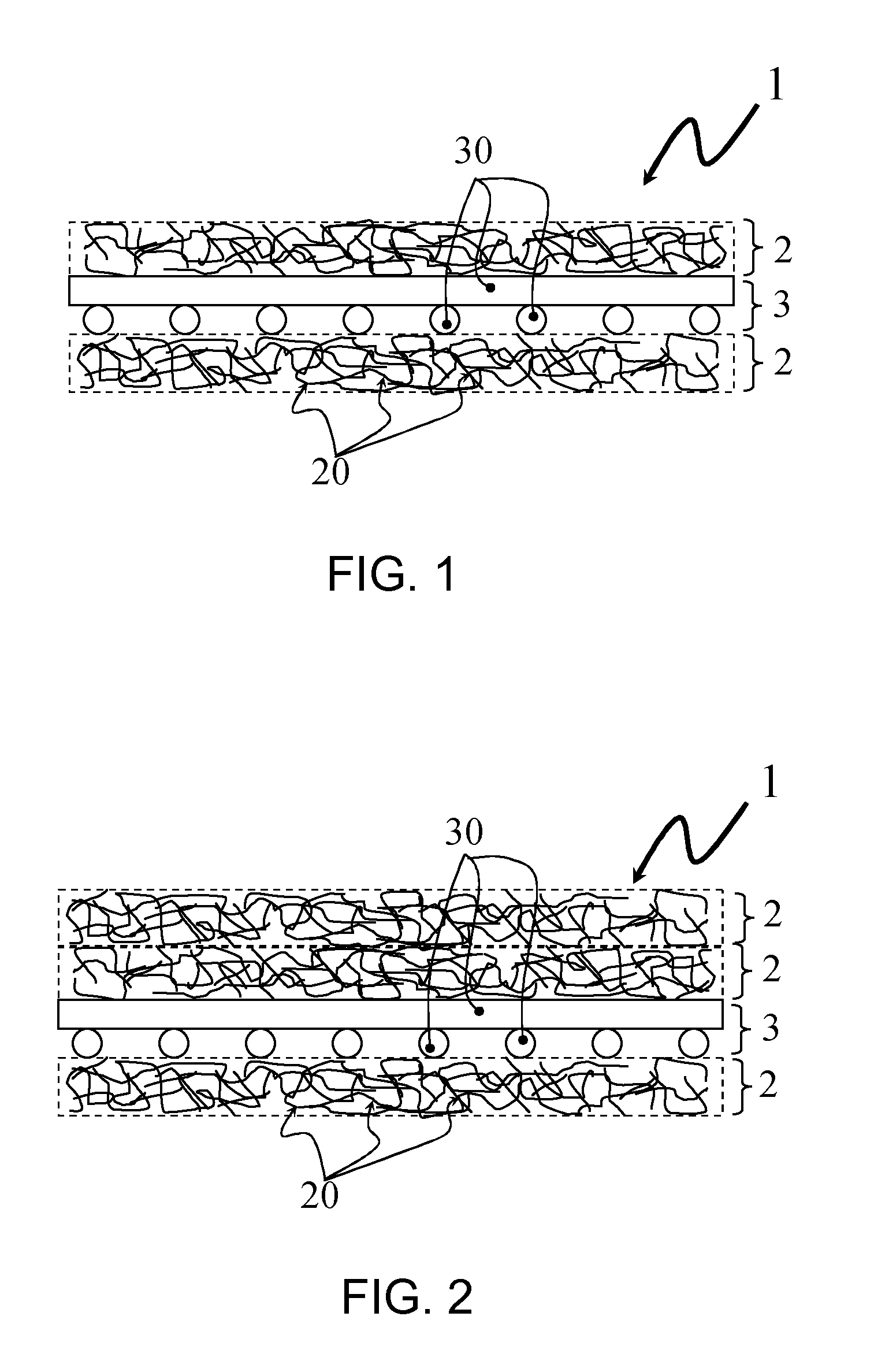
[0025]FIG. 2 shows the schematic structural design of a preferred embodiment of the flat textile structure (1) according to the invention. Two vertically stacked pile layers (2) here lie on one side of the reinforcing grid (3), while one pile layer (2) lies on the other side. This embodiment is preferred because the surface of the flat textile structure (1) exhibits better optical and tactile characteristics on the side with the two vertically stacked pile layers (2). This becomes advantageous when primarily only one side of the component is visible in the subsequent component that integrates the flat textile structure (1), for example in the case of vehicl...


PUM

PropertyMeasurementUnit
angleaaaaaaaaaa
angleaaaaaaaaaa
angleaaaaaaaaaa

Abstract

A flat textile structure has a reinforcing grid and at least one pile layer which is placed flat on at least one surface of the reinforcing grid. The flat textile structure has a weight per unit area of from 40 to 140 g / m2. The pile layer is formed predominantly of carbon fibers. The carbon fibers in the flat textile structure have a proportion of the weight per unit area of from 60 to 97%, the reinforcing grid has a proportionate weight per unit area of from 2.5 to 12.5 g / m2 and the flat textile structure is strengthened.

Description

AREA OF THE INVENTION[0001]The present invention relates to a woven material that has been reinforced for improved handling during the manufacturing process, a component incorporating the reinforced nonwoven material, and its use. In particular, the present invention relates to a carbon fiber nonwoven with a reinforcing grid contained therein.BACKGROUND OF THE INVENTION[0002]During the manufacture of flat textile structures with a relatively low cohesion among the textile fibers, for example in the case of nonwoven or pile, the simplest handling processes can pose a problem, such as rolling the flat structures on and off, and automatically feeding them to additional production stages. One possible way of countering this problem is to integrate a reinforcing grid into the flat structure. This basic structure of reinforcing layers incorporated between pile layers represents the starting point of the present invention.[0003]Disclosed in DE 92 07 367 U1 is a laminate whose surfaces were...

Claims


Application Information

Patent Timeline
Patent Type & Authority Applications(United States)
IPC IPC(8): D04H11/00
CPCB29B11/16B32B2605/08D04H1/06D04H1/4242D04H1/4274D04H1/4374D04H1/46D04H1/498D04H1/74D04H3/045D04H5/02D01G1/04D01G7/00D01G13/00D04H11/00D01G15/00B32B5/022B32B5/028B32B5/06B32B7/12B32B2250/20B32B2262/0276B32B2262/101B32B2262/106B32B2307/40B32B2307/50B29C70/081Y10T428/23993Y10T428/23929Y10T428/23964Y10T428/23957Y10T428/23979B32B5/26
Inventor DANZER, MARTIN
Owner SGL AUTOMOTIVE CARBON FIBERS
Why Eureka
Try Eureka