Automated Method of Pooling Elimination with a Biological Fluid Collection System

a biological fluid and automatic method technology, applied in the field of automatic method of pooling elimination with biological fluid collection system, can solve the problems of difficult to accurately determine how much urine actually exited the bladder, significant amount of urine can remain, and urine output readings cannot be accurately determined in this way

Inactive Publication Date: 2013-08-22
CR BARD INC
View PDF28 Cites 36 Cited by
  • Summary
  • Abstract
  • Description
  • Claims
  • Application Information

AI Technical Summary

Benefits of technology

[0007]According to one non-limiting embodiment of the invention, there is provided a drainage system for biological fluids which comprises a control device for supplying continuous or intermittent gas flow, e.g., a steady stream or pulses of air, to at least one conduit s...

Problems solved by technology

With known systems, a significant amount of urine can remain or pool in the conduit and does not easily pass into the collection vessel.
As such, it is difficult to determine accurately how much urine actually exited from the bladder.
Urine output readings can thus not be accurately determined this way.
While it is possible to manipulate or move (or “milk”) the conduit so that some urine trapped in the conduit can be forced or flushed via gravity into the collection vess...

Method used


Image

  • Automated Method of Pooling Elimination with a Biological Fluid Collection System
  • Automated Method of Pooling Elimination with a Biological Fluid Collection System
  • Automated Method of Pooling Elimination with a Biological Fluid Collection System

Examples


Embodiment Construction

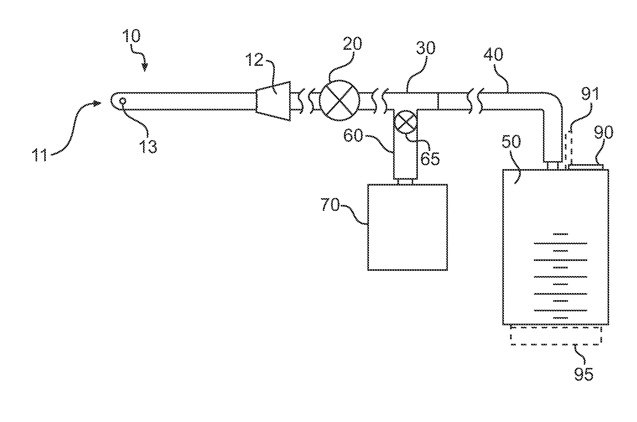
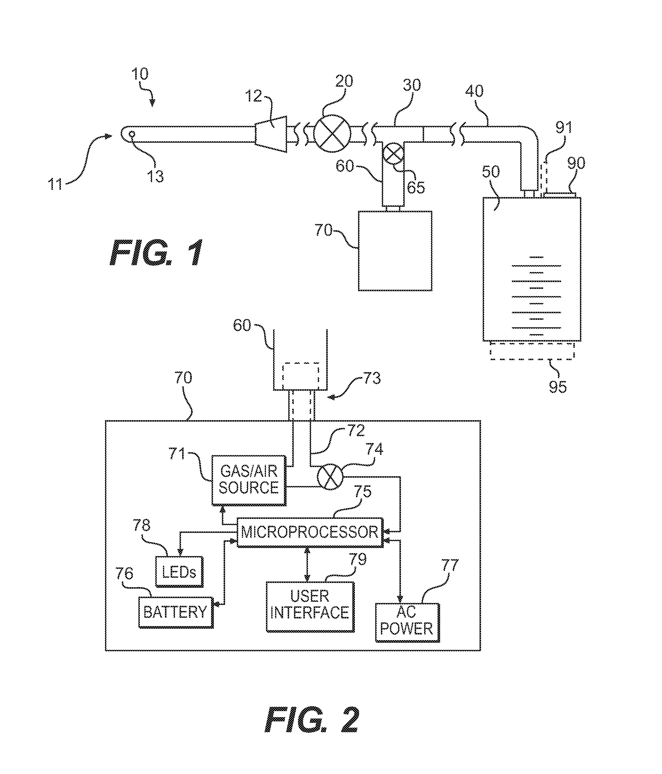
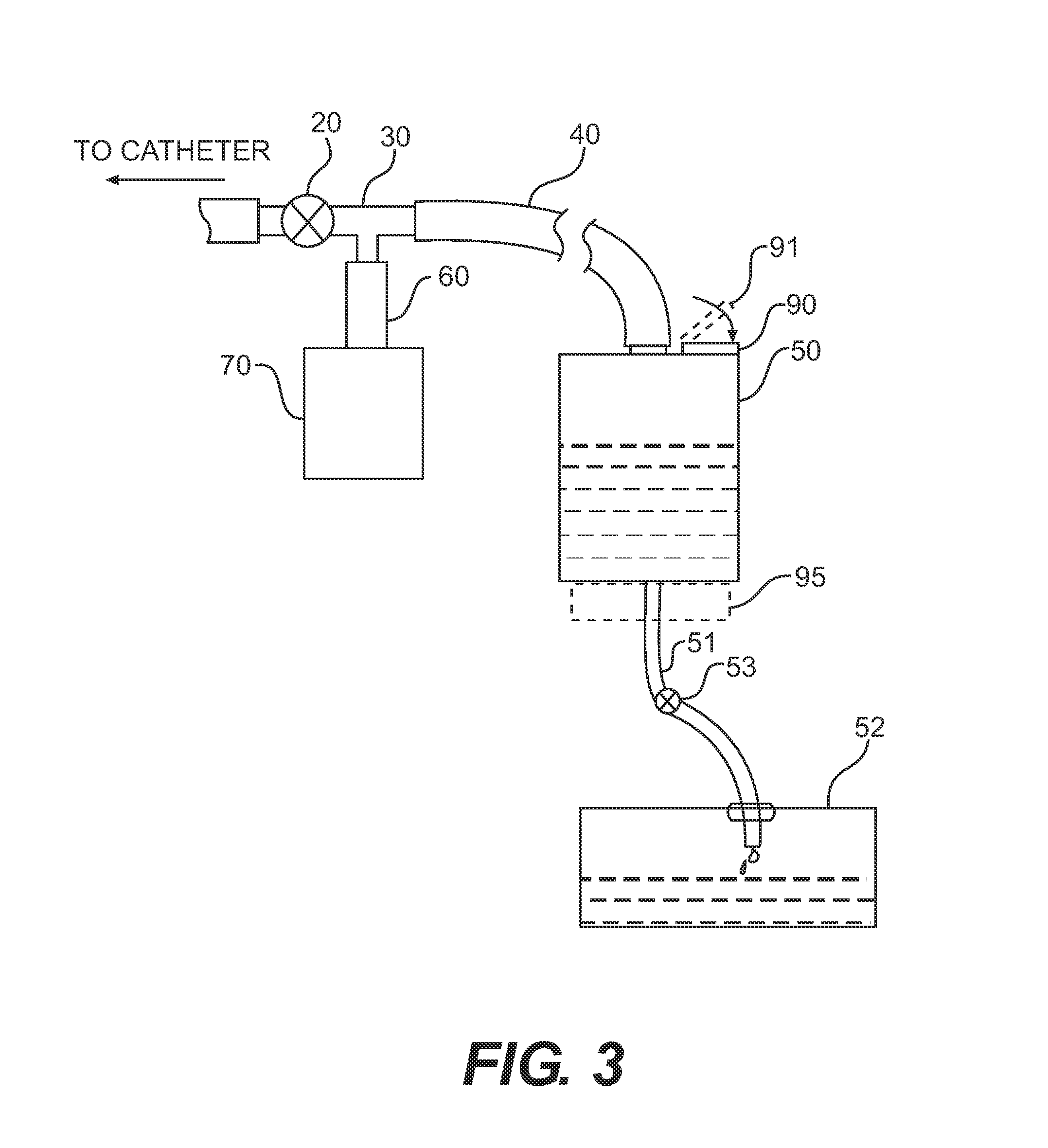
[0040]The following description should be read with reference to the drawings, in which like elements in different drawings are identically numbered. The drawings, which are not necessarily to scale, depict selected embodiments and are not intended to limit the scope of the invention. The detailed description illustrates by way of example, not by way of limitation, the principles of the invention. This description will enable one skilled in the art to make and use the invention, and describes several embodiments, adaptations, variations, alternatives and uses of the invention, including what is presently believed to be the best mode of carrying out the invention.

[0041]As used herein, the reference terms “proximal” and “distal” (proximal being closer than distal) refer to proximity with respect to a health care professional catheterizing a patient. For example, the region or section of the catheter apparatus that is closest to the health care professional during catheterization is re...


PUM


Abstract

A drainage and/or collection system for biological fluids includes at least one conduit for transporting a biological fluid from a catheter to a collector device and a gas pressure source configured to feed a gas into the at least one conduit between the catheter and the collection device. The gas causes the biological fluid arranged in the at least one conduit to drain into the collection device. A method includes inserting a catheter, draining a fluid into a collector device via a conduit, and introducing gas into the conduit so as to force fluid remaining in the conduit into the collection device.

Description

CROSS REFERENCE TO RELATED APPLICATIONS[0001]This application claims benefit of priority to U.S. Provisional Application No. 61 / 369,494, filed Jul. 30, 2010, and entitled “Automated Method of Pooling Elimination with a Biological Fluid Collection System,” the contents of which are incorporated herein by reference.STATEMENT CONCERNING GOVERNMENT INTEREST[0002]Not applicable.BACKGROUND OF THE INVENTION[0003]Catheterization is a sterile process of draining urine from the bladder. Typically, a catheter is inserted into a bladder so that fluid can pass out through the catheter, into a conduit and then into a collection vessel. The amount of urine in the collection vessel is then measured.[0004]With known systems, a significant amount of urine can remain or pool in the conduit and does not easily pass into the collection vessel. As such, it is difficult to determine accurately how much urine actually exited from the bladder. Urine output readings can thus not be accurately determined this...

Claims


Application Information

Patent Timeline
IPC IPC(8): A61M1/00
CPCA61B5/207A61M1/0023A61M2202/0496A61M2205/07A61M1/00A61M2205/3382A61M2205/3393A61M2206/20A61M2205/3375A61M1/71A61M1/78A61M1/73A61M1/83
Inventor COSTON, ANTHONYCICCONE, PAUL
Owner CR BARD INC
Why Eureka
Try Eureka