Fixing mechanism for fixing an accessory on a portable electronic device

Active Publication Date: 2013-08-29
WISTRON CORP
View PDF5 Cites 2 Cited by
  • Summary
  • Abstract
  • Description
  • Claims
  • Application Information

AI Technical Summary

Benefits of technology

[0024]The fixing mechanism of the present invention utilizes the mechanical design that a direction of fixing the accessory is identical to a direction of sliding the sliding key for not only providing a user with a good sense of operation, but also for preventing the accessory from easily separating from the portable ele

Problems solved by technology

A user is easily to touch other external components as operating the key, so as to result in bad feeling of operation.
As a result, a fixing me

Method used


Image

  • Fixing mechanism for fixing an accessory on a portable electronic device
  • Fixing mechanism for fixing an accessory on a portable electronic device
  • Fixing mechanism for fixing an accessory on a portable electronic device

Examples


Embodiment Construction

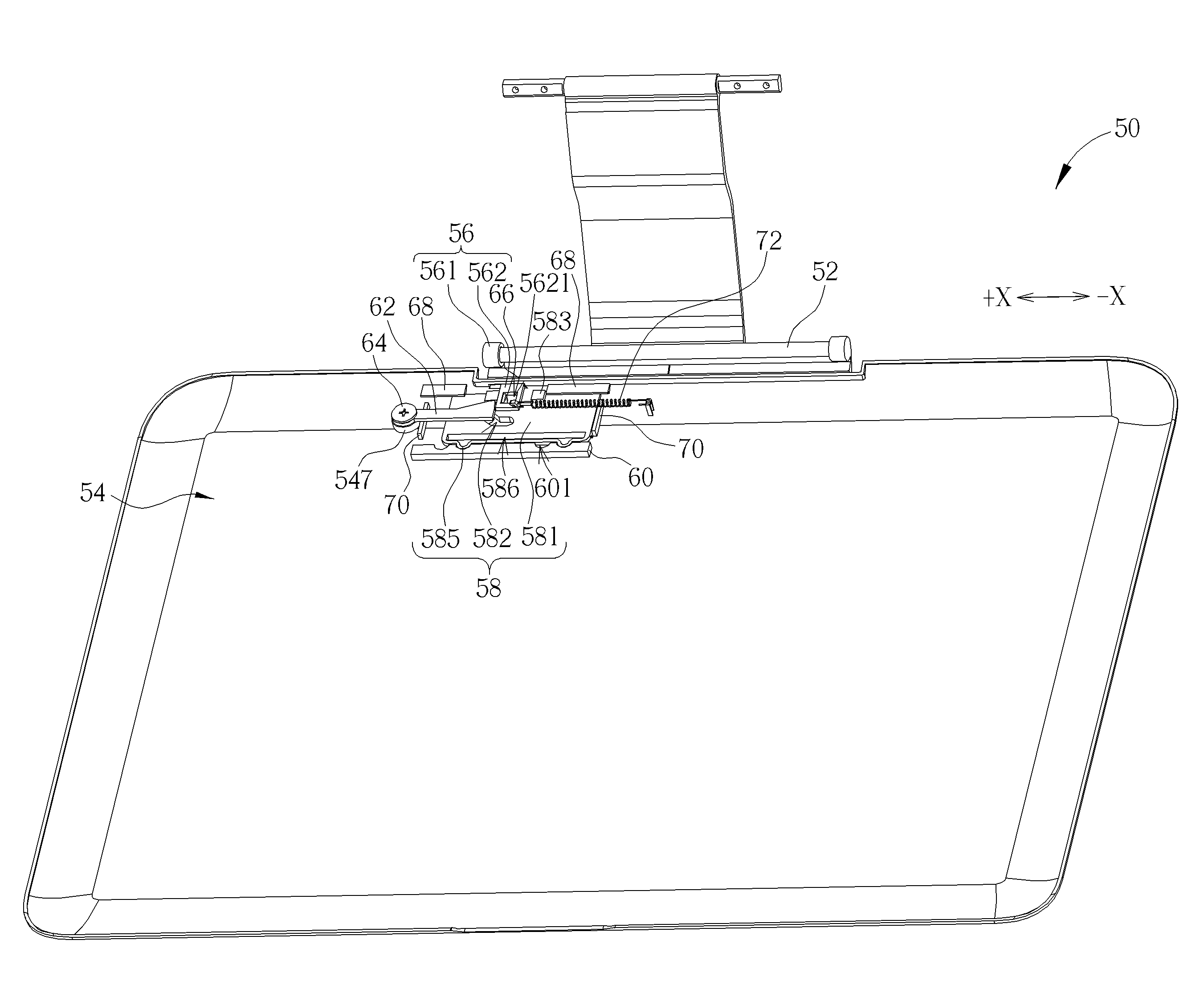
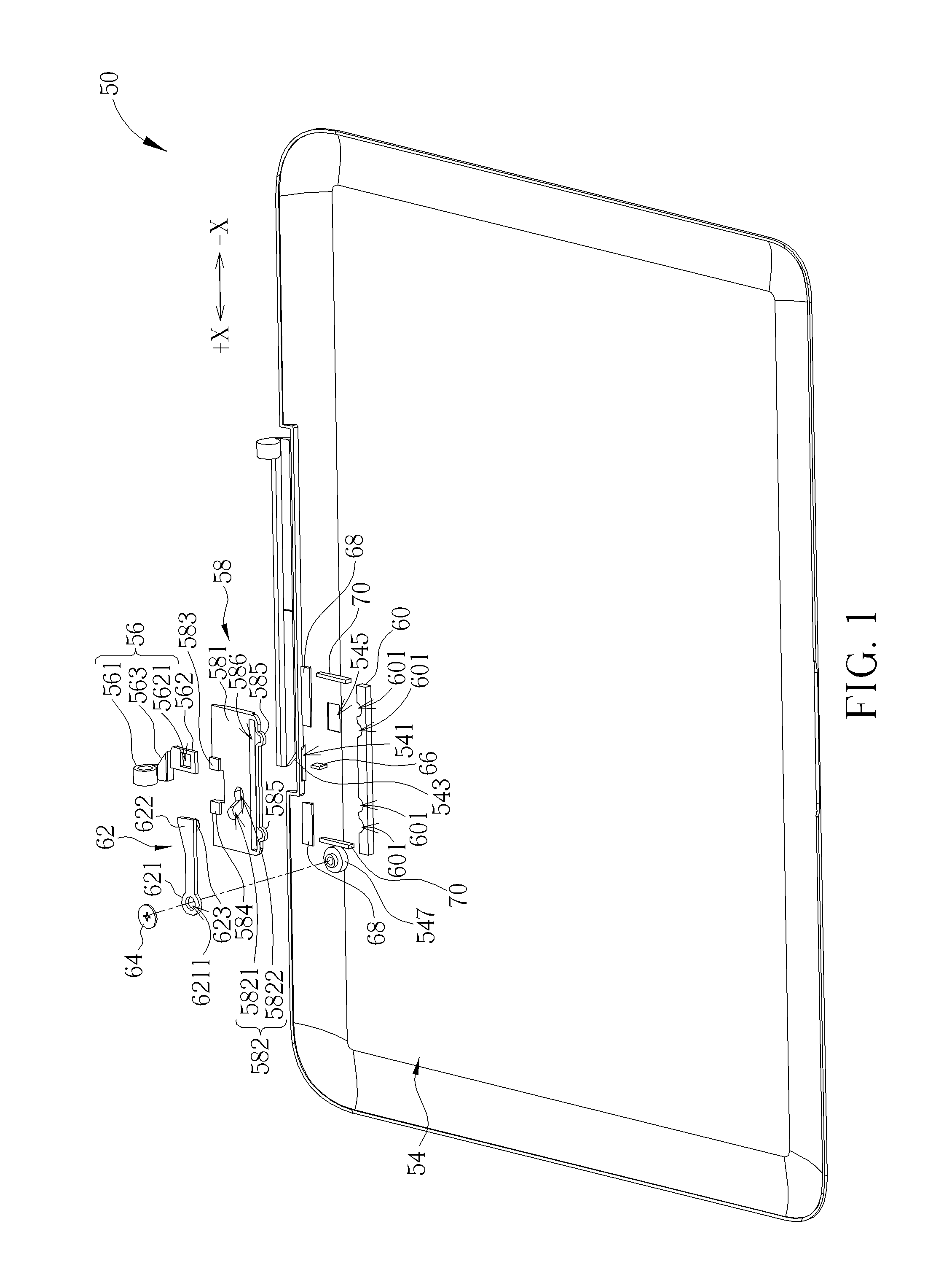
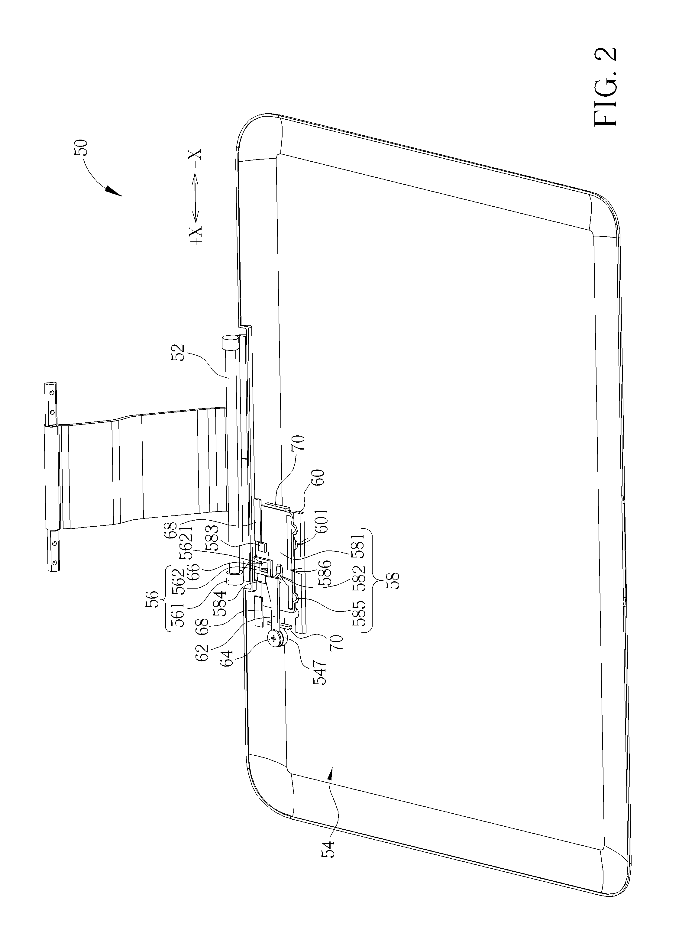
[0032]Please refer to FIG. 1 and FIG. 2. FIG. 1 and FIG. 2 are respectively an exploded diagram and an assembly diagram of a fixing mechanism 50 according to an embodiment of the present invention. The fixing mechanism 50 is used for fixing an accessory 52 on a portable electronic device, such as for fixing an external hard disk drive on a tablet computer and so on. The fixing mechanism 50 includes a base 54 whereon an opening 541 and an inclined structure 543 are formed. The base 54 can be an external casing of the portable electronic device. The fixing mechanism 50 further includes a movable hook 56 disposed through the opening 541 on the base 54 in a slidable manner. Please refer to FIG. 1 to FIG. 3. FIG. 3 is a diagram of the movable hook 56 according to the embodiment of the present invention. A first end 561 of the movable hook 56 is used for fixing the accessory 52. For example, the first end 561 of the movable hook 56 can be a hook for hooking an end of the accessory 52. A s...


PUM


Abstract

A fixing mechanism includes a base, a movable hook and a sliding key. A first end of the movable hook is for fixing an accessory. The sliding key is slidably installed on the base. The sliding key includes a key body whereon a sliding slot is formed, and a driving part for pushing a second end of the movable hook when the key body moves in a first direction so as to separate the first end of the movable hook from the accessory. The fixing mechanism further includes a rotary arm. A first end of the rotary arm is rotatably installed on the base, and a second end of the rotary arm is slidably installed inside the sliding slot. The second end of the rotary arm stops the second end of the movable hook in a closed position for preventing the movable hook from moving in the first direction.

Description

BACKGROUND OF THE INVENTION[0001]1. Field of the Invention[0002]The present invention relates to a fixing mechanism, and more particularly, to a fixing mechanism for fixing an accessory on a portable electronic device.[0003]2. Description of the Prior Art[0004]With growth of requirement of a consumer electronic product, it has been one of the main considerations for the modern consumer electronic product to be coupled to an accessory. For example, a tablet computer with thin, light and short designs and capable of being coupled to a variety of accessories has been a trend in the market. The tablet computer with the aforesaid designs has possessed portability and ability to expand functions. However, the conventional design for the tablet computer to be coupled to the accessory is to adopt a mechanism with an assembly direction perpendicular to a locking / unlocking direction of a key. A user is easily to touch other external components as operating the key, so as to result in bad feel...

Claims


Application Information

Patent Timeline
IPC IPC(8): H05K7/14
CPCH05K7/1417G06F1/1626Y10T403/70G06F1/1681Y10T403/602G06F1/1656
Inventor LIANG, CHEN-YICHEN, CHUN-CHIEN
Owner WISTRON CORP
Why Eureka
Try Eureka