High order shaped curve region for an airfoil

a high-order, airfoil technology, applied in the field of airfoils, can solve the problems of reducing the ability of the compressor section to sustain pressure rise, increasing losses, and affecting the stall margin

Active Publication Date: 2013-08-29
RAYTHEON TECH CORP
View PDF6 Cites 76 Cited by
  • Summary
  • Abstract
  • Description
  • Claims
  • Application Information

AI Technical Summary

Benefits of technology

[0007]In one non-limiting disclosed embodiment, a turbomachine blade has: an airfoil extending along a spanwise stacking distribution between a root and a tip region, the airfoil including a chordline extending between a leading edge and a trailing edge; and a dihedral feature of the spanwise stack...

Problems solved by technology

Tip clearance flow reduces the ability of the compressor section to sustain pressure rise, increases losses and may have a negative impact on stall margin (i.e., the point at which the compressor section can n...

Method used


Image

  • High order shaped curve region for an airfoil
  • High order shaped curve region for an airfoil
  • High order shaped curve region for an airfoil

Examples


Embodiment Construction

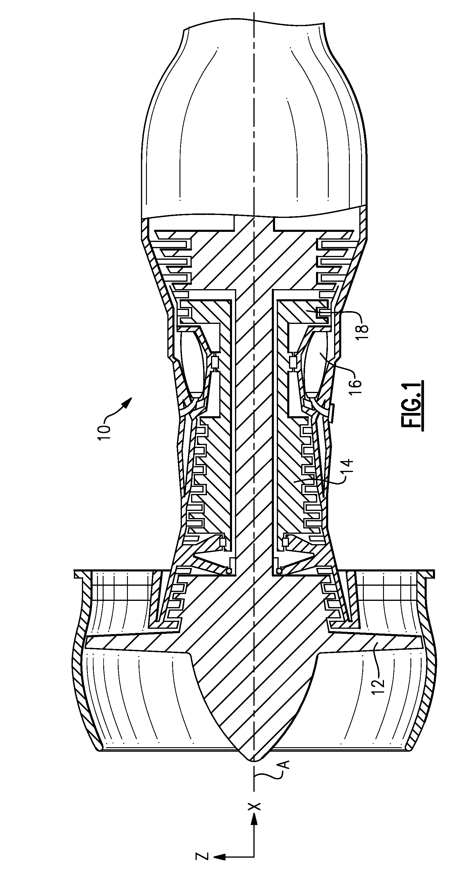
[0047]FIG. 1 illustrates an example gas turbine engine 10 that includes a fan 12, a compressor section 14, a combustor section 16 and a turbine section 18. The gas turbine engine 10 is defined about an engine centerline axis A about which the various engine sections rotate. Air is drawn into the gas turbine engine 10 by the fan 12 and flows through the compressor section 14 to pressurize the airflow. Fuel is mixed with the pressurized air and combusted within the combustor 16. The combustion gases are discharged through the turbine section 18, which extracts energy therefrom for powering the compressor section 14 and the fan 12. Of course, this view is highly schematic. In the illustrated example, the gas turbine engine 10 is a turbofan gas turbine engine. It should be understood, however, that the features and illustrations presented within this disclosure are not limited to a turbofan gas turbine engine. That is, the present disclosure is applicable to any axial flow turbine machi...


PUM


Abstract

A turbomachine blade with a localized dihedral feature has a high order polynomial shaped curve region.

Description

REFERENCE TO RELATED APPLICATIONS[0001]The present application claims priority to U.S. Provisional Patent Application No. 61 / 605,019, filed Feb. 29, 2012.TECHNICAL FIELD[0002]The present disclosure is related in general to airfoils for use in turbine machines, and in particular to airfoils incorporating localized high order dihedral.BACKGROUND OF THE INVENTION[0003]Turbine machines, such as turbofan gas turbine engines or land based turbine generators, typically include a compressor section, a combustor section and a turbine section. During operation, air is pressurized in the compressor section and mixed with fuel in the combustor section for generating hot combustion gases. The hot combustion gases flow through the turbine section which extracts energy from the hot combustion gases to power the compressor section and in the case of turbine generators, drive the turbine power shaft.[0004]Many turbine machines include axial-flow type compressor sections in which the flow of compress...

Claims


Application Information

Patent Timeline
IPC IPC(8): F01D5/14
CPCF01D5/141F05D2240/307F01D5/20F05D2200/22F05D2240/125F05D2240/305F05D2250/71Y10S416/02Y10S416/05
Inventor STRACCIA, JOSEPH C.
Owner RAYTHEON TECH CORP
Why Eureka
Try Eureka