Heat Dissipation Structure of Tire Repair Machine

a tire repair machine and heat dissipation structure technology, applied in the direction of machines/engines, positive displacement liquid engines, lighting and heating apparatus, etc., can solve the problems of tire pressure loss, increase fuel consumption, and not run, and achieve effective heat dissipation and reasonable airflow path

Inactive Publication Date: 2013-09-05
ACTIVE TOOLS INTERNATIONAL (HK) LIMITED
View PDF9 Cites 15 Cited by
  • Summary
  • Abstract
  • Description
  • Claims
  • Application Information

AI Technical Summary

Benefits of technology

[0008]In the heat dissipation structure of the tire repair machine provided by the present invention, a positioning pedestal having at least one channel is provided inside the body, wherein a channel inlet and a channel outlet are provided at the two ends of the channel respectively; a gas supply unit arranged inside the body comprises a motor and an air compressor driven by the motor; the motor is arranged at the rear of the positioning pedestal, such that the radial direction of a centrifugal fan connected with the drive shaft of the motor is directed to the channel inlet, while the air compressor is corresponding to the channel outlet; when the motor drives the air compressor to run, the air drawn in by the centrifugal fan can blow the air compressor via the channel, so as to perform heat dissipation for the air compressor.
[0010]In the present invention, a tailgate is provided at the rear end of the body. The tailgate is provided with two or more ventilation holes. A filter is provided between the tailgate and the positioning pedestal. During the running of the centrifugal fan, the air is drawn in from outside of the body via the ventilation hole, and then passes through the filter; after that, it is leaded into the channel to blow the air compressor to perform heat dissipation for the air compressor. As the air flows through the channel, it can absorb the heat produced by the motor simultaneously to implement the heat dissipation effect on the motor.

Problems solved by technology

The vehicle can not run after its tire ruptures and the tire pressure is lost.
However, the weight of the tire together with the rim will increase that of the vehicle body, and consequently increase the fuel consumption.
This is neither economical nor environmental friendly.
The actual test and analysis show that, for the tire repair machine, two fans in one body are over many and unnecessary.

Method used


Image

  • Heat Dissipation Structure of Tire Repair Machine
  • Heat Dissipation Structure of Tire Repair Machine
  • Heat Dissipation Structure of Tire Repair Machine

Examples


Embodiment Construction

[0045]100191 Below the implementation of the present invention is explained in more detail in coordination with schemas and component symbols so that those skills familiar with this technology can practice the present invention after reading the specification.

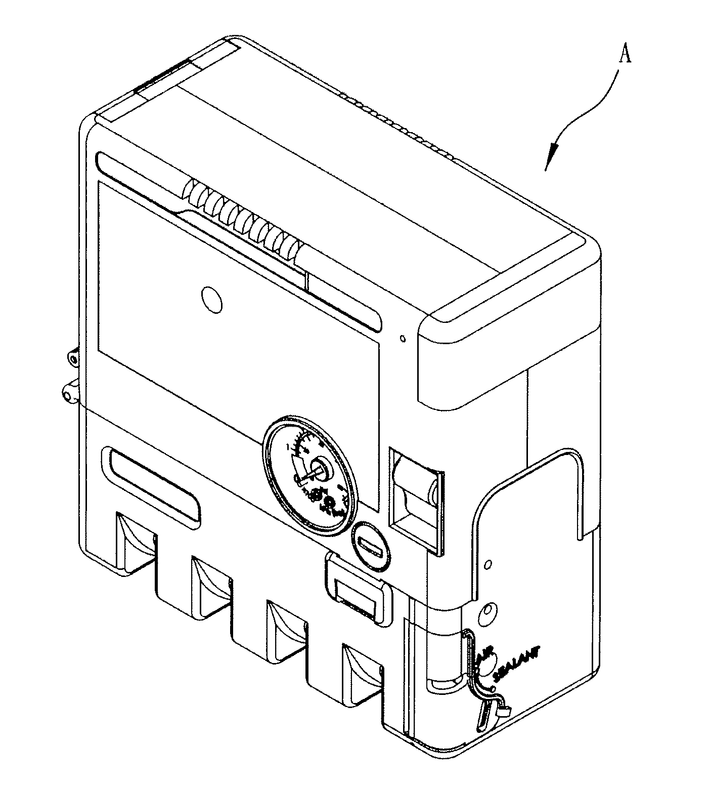
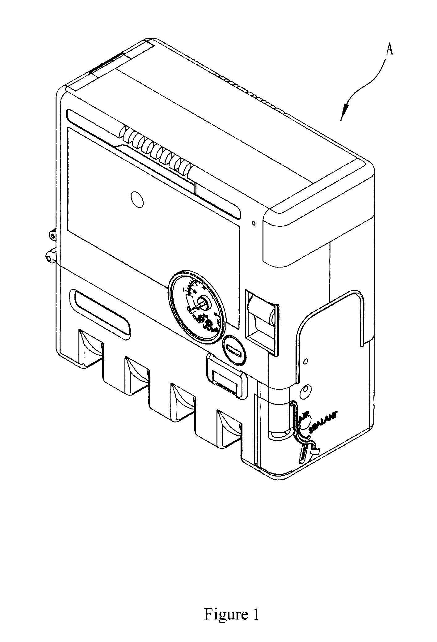
[0046]The heat dissipation structure provided by the present invention is generally applied to the tire repair machine A shown in FIG. 1.

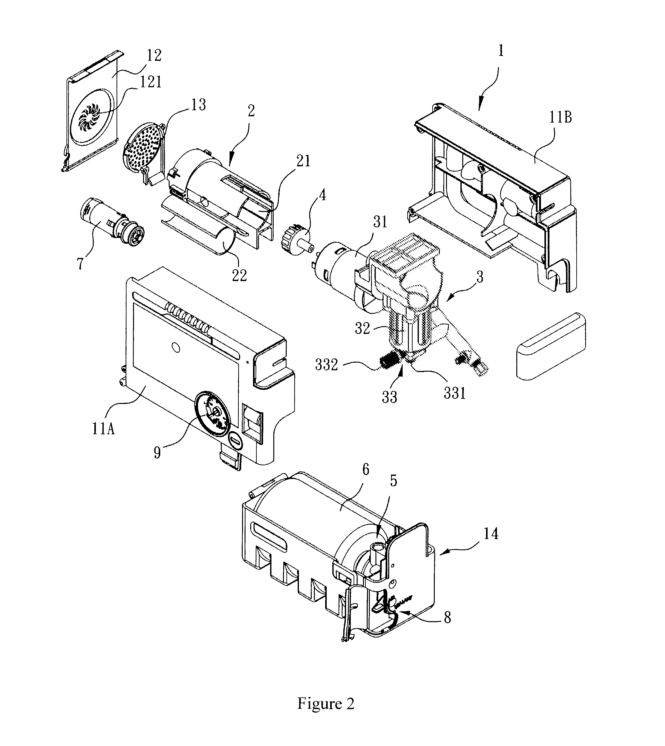
[0047]As shown in FIGS. 2, 3 and 4, in a preferred embodiment, the heat dissipation structure according to the present invention comprises a body 1 composed of a first upper housing 11A, a second upper housing 11B and a base 14. Wherein, the base 14 is used for accommodating a sizing barrel 6 and a joint base connected with the outlet of the sizing barrel 6. The first upper housing 11A combined with the second upper housing 11B are provided above the base 14, and an inner room formed by the first upper housing 11A together with the second upper housing 11B is used for accommodating a positioni...


PUM

PropertyMeasurementUnit
heataaaaaaaaaa
heat dissipationaaaaaaaaaa
pressureaaaaaaaaaa

Abstract

The present invention discloses a heat dissipation structure of the tire repair machine, wherein, a positioning pedestal having at least one channel is provided inside the body, a channel inlet and a channel outlet are provided at the two ends of the channel respectively; a gas supply unit arranged inside the body comprises a motor and an air compressor driven by the motor, the motor is arranged at the rear of the positioning pedestal, such that the radial direction of a centrifugal fan connected with the drive shaft of the motor is directed to the channel inlet, while the air compressor is corresponding to the channel outlet; when the motor drives the air compressor to run, the air drawn in by the centrifugal fan can blow the air compressor via the channel, so as to perform heat dissipation for the air compressor.

Description

CROSS-REFERENCE TO RELATED APPLICATIONS[0001]Pursuant to 35 U.S.C. 119(a), the instant application claims priority to prior Taiwan application number 101203944, filed Mar. 5, 2012.FIELD OF THE INVENTION[0002]The present invention relates to a heat dissipation structure, and particularly to an improved structure by means of windhole for guiding the airflow outside of the body into the body by use of a fan, so as to blow an air compressor to perform heat dissipation.BACKGROUND OF THE INVENTION[0003]The vehicle can not run after its tire ruptures and the tire pressure is lost. Such that, only the tire is replaced or repaired and then inflated, can the vehicle go on. Accordingly, the vehicle is generally equipped with a spare tire as required. However, the weight of the tire together with the rim will increase that of the vehicle body, and consequently increase the fuel consumption. This is neither economical nor environmental friendly. In order to reduce the vehicle load produced by on...

Claims


Application Information

Patent Timeline
Patent Type & Authority Applications(United States)
IPC IPC(8): H01L23/467
CPCB29L2030/00F04B39/066B29C73/166F04D25/082
Inventor HONG, DAVID
Owner ACTIVE TOOLS INTERNATIONAL (HK) LIMITED
Why Eureka
Try Eureka