
Image forming apparatus and toner supply control method

a technology of toner supply control and forming apparatus, which is applied in the direction of electrographic process apparatus, instruments, optics, etc., can solve the problems of the development device to be mixed by the developer

Inactive Publication Date: 2013-09-05
RICOH KK
View PDF2 Cites 31 Cited by
  • Summary
  • Abstract
  • Description
  • Claims
  • Application Information

AI Technical Summary

Benefits of technology

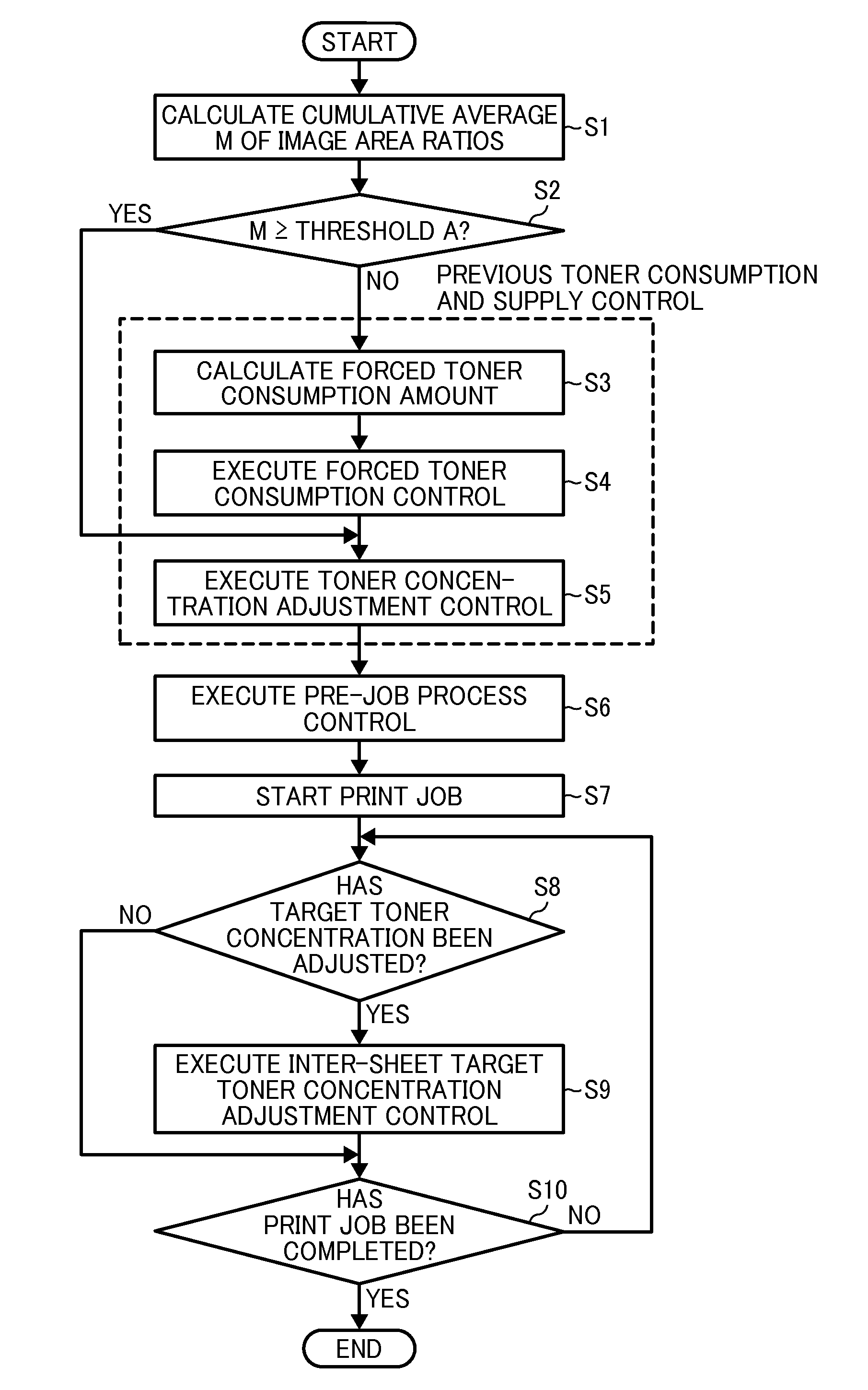
The present invention provides an image forming apparatus with a latent image carrier, development device, toner supply device, forced toner consumption control, pre-job controller, image density adjustment controller, and detector. The pre-job controller determines a specific target image density based on the acquired toner consumption index value and adjusts one or more image forming conditions to make the image density approach the specific target image density. The detector detects the toner amount adhering to the toner pattern and adjusts the image density accordingly. The image forming apparatus also includes a carrier deterioration index value storage device and a retention time storage device to determine the specific target image density. The image forming apparatus can also include a toner supply control method that includes acquiring the input of the image forming job, acquiring the toner consumption index value, determining a specific target image density, and executing a forced toner consumption control to cause the toner in the development device to adhere to a non-image area in a surface of the latent image.

Problems solved by technology

The pre-job controller may cause the developer in the development device to be mixed after the previous toner consumption and supply control and before the previous image density adjustment control.

Method used


Image

  • Image forming apparatus and toner supply control method
  • Image forming apparatus and toner supply control method
  • Image forming apparatus and toner supply control method

Examples


Embodiment Construction

[0050]In describing the embodiments illustrated in the drawings, specific terminology is adopted for the purpose of clarity. However, the disclosure of the present invention is not target to be limited to the specific terminology so used, and it is to be understood that substitutions for each specific element can include any technical equivalents that have the same function, operate in a similar manner, and achieve a similar result.

[0051]Referring now to the drawings, wherein like reference numerals designate identical or corresponding parts throughout the several views, an embodiment of an electrophotographic printer will be described as an image forming apparatus according to an embodiment of the present invention. A description will first be given of a basic configuration of a printer 1 according to the present embodiment. FIG. 5 is a schematic configuration diagram illustrating the printer 1 according to the present embodiment. In FIG. 5, the printer 1 includes a printer body 10...


PUM


Abstract

An image forming apparatus includes a forced toner consumption controller which executes a forced toner consumption control; a toner supply controller which executes a toner supply control; and a pre-job controller which, upon receipt of an image forming job, and before the start of the job, acquires a toner consumption index value, determines a specific target image density based on the acquired index value, executes a previous toner consumption and supply control including the forced toner consumption control and the toner supply control that makes a toner concentration in a developer of a development device subjected to the forced toner consumption control approach a specific target toner concentration, and then executes a previous image density adjustment control that adjusts one or more image forming conditions to make an image density after the previous toner consumption and supply control approach the specific target image density.

Description

CROSS-REFERENCE TO RELATED APPLICATION[0001]This patent application is based on and claims priority pursuant to 35 U.S.C. §119 to Japanese Patent Application No. 2012-047999, filed on Mar. 5, 2012 in the Japan Patent Office, the entire disclosure of which is hereby incorporated by reference herein.BACKGROUND OF THE INVENTION[0002]1. Field of the Invention[0003]The present invention relates to an image forming apparatus, such as a copier, a printer, or a facsimile machine, and more specifically to an image forming apparatus which forms an image with a two-component developer including toner and carrier, and to a toner supply control method for the image forming apparatus.[0004]2. Description of the Related Art[0005]In an electrophotographic image forming apparatus, upon receipt of an input of an image forming job, such as a print job, a latent image carrier is driven to rotate and an outer circumferential surface of the rotating latent image carrier is uniformly charged to a target c...

Claims


Application Information

Patent Timeline
IPC IPC(8): G03G15/08
CPCG03G15/556G03G15/0865G03G15/0853G03G15/0832
Inventor ISHII, HIROKI
Owner RICOH KK
Features
  • Generate Ideas
  • Intellectual Property
  • Life Sciences
  • Materials
  • Tech Scout
  • Unparalleled Data Quality
  • Higher Quality Content
  • 60% Fewer Hallucinations
Learn More