

Inertial force sensor
a sensor and force technology, applied in the field ofinertial force sensors, can solve problems such as output offsets, and achieve the effect of reducing output offsets
- Summary
- Abstract
- Description
- Claims
- Application Information
AI Technical Summary
Benefits of technology
Problems solved by technology
Method used
Image


Examples
exemplary embodiment 1
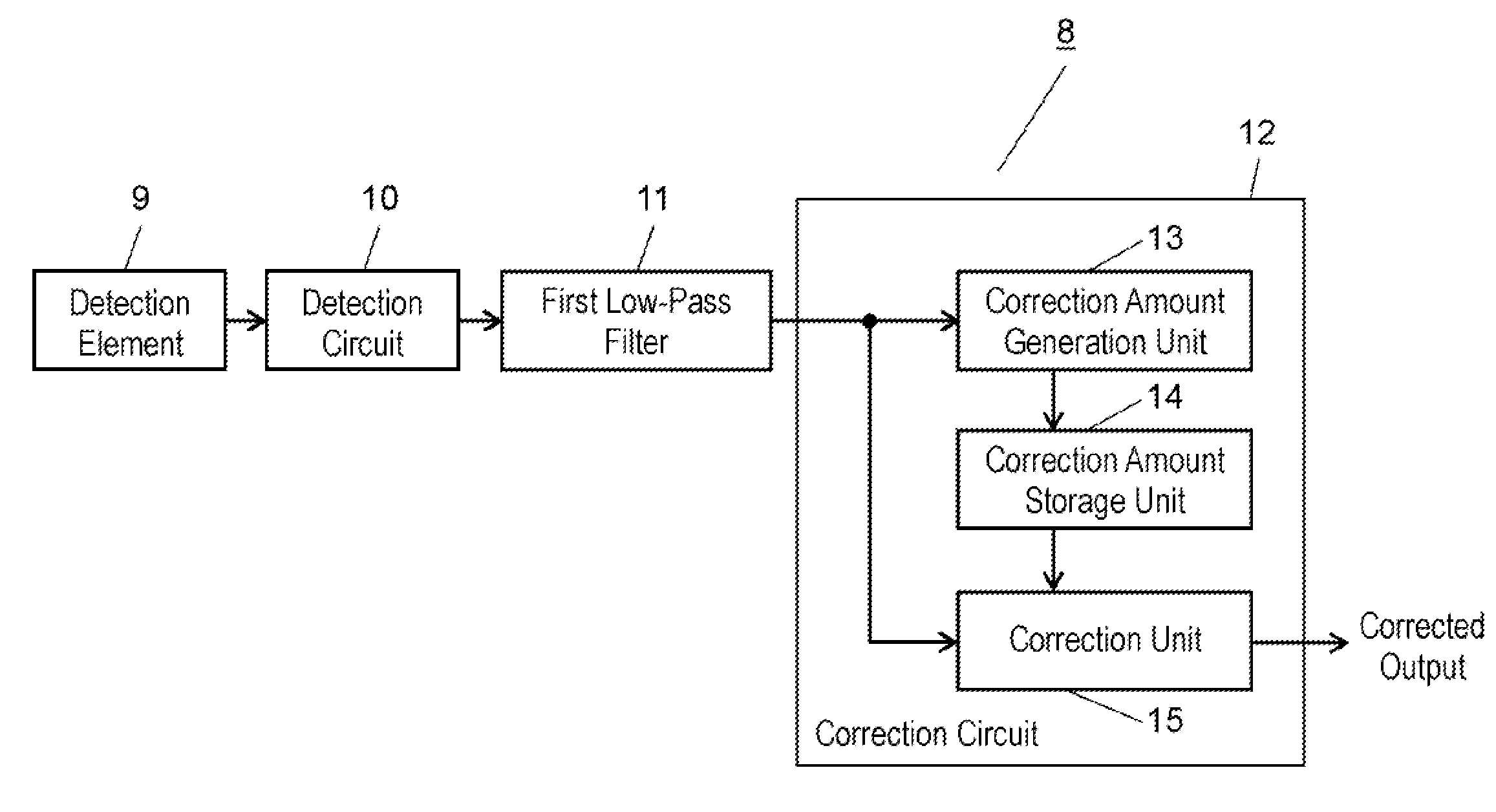
[0023]FIG. 1 is a block diagram of an inertial force sensor according to Exemplary Embodiment 1.
[0024]As shown in FIG. 1, inertial force sensor 8 includes detection element 9, detection circuit 10 for detecting the amount, of inertia corresponding to an to inertial force applied to detection element 9, first low-pass filter 11 connected to the output side of detection circuit 10, and correction circuit 12 for correcting the output of first low-pass filter 11. Correction circuit 12 includes correction amount generation unit 13 connected to the output side of first low-pass filter 11, correction amount storage unit 14 connected to the output side of correction amount generation unit 13, and correction unit 15 connected to the output side of first low-pass filter 11 and to the output side of correction amount storage unit 14.
[0025]Correction unit 15 corrects the output value of first low-pass filter 11 based on the correction amount stored in correction amount storage unit 14.
[0026]Thi...
exemplary embodiment 2
[0041]A difference of a sensor according to Exemplary Embodiment 2 of the present invention from Embodiment 1 will be described below.
[0042]FIG. 6 is a block diagram of an inertial force sensor according to Embodiment 2.
[0043]As shown in FIG. 6, inertial force sensor 19 includes correction amount generation unit 13d including second low-pass filter 13e. Second low-pass filter 13e is connected to the output side of first low-pass filter 11, whereas the output of second low-pass filter 13e is connected to correction amount storage unit 14. First low-pass filter 11 has a cut-off frequency higher than a cut-off frequency of second low-pass filter 13e. This configuration can extract a frequency component lower than the cut-off frequency of second low-pass filter 13e as an output offset.
[0044]Thus, correction amount generation unit 13d including second low-pass filter 13e can eliminate calculation circuit 13c included in the configuration shown in FIG. 5, thereby reducing the circuit area...
exemplary embodiment 3
[0045]A difference of a sensor according to Exemplary Embodiment 3 from Embodiment 1 will be described below.
[0046]FIG. 7 is a block, diagram of an inertial force sensor according to Embodiment 3.
[0047]As shown in FIG. 7, inertial force sensor 20 includes inertia amount determination unit 16 in correction circuit 12. Inertia amount determination unit 16 determines whether or not the correction amount stored in correction amount storage unit 14 is the amount of inertia. If the stored correction amount is the amount of inertia, inertia amount determination unit 16 outputs an instruction signal. If the stored correction amount is not the amount of inertia, inertia amount determination unit 16 does not output the instruction signal.
[0048]If the instruction signal from inertia amount determination unit 16 is input to correction amount storage unit 14, correction amount storage unit 14 maintains the stored correction amount output from correction amount generation unit 13, and does not up...
PUM
 Abstract
Description
Claims
Application Information