Centrifuge comprising visual and/or tactile indicator for indicating the accurate mounting of the rotor on the drive shaft, and corresponding rotor

a technology of centrifuges and indicators, which is applied in the direction of centrifuges, clutches, couplings, etc., can solve the problems of insufficient axial locking, affecting and affecting the safety of the personnel present in the vicinity of the centrifuge, so as to achieve easy detection by touch and increase the cooperation of the male element

Inactive Publication Date: 2013-09-12
BMS INT
View PDF24 Cites 16 Cited by
  • Summary
  • Abstract
  • Description
  • Claims
  • Application Information

AI Technical Summary

Benefits of technology

[0029]or pass his fingers around the annular cage, the protruding presence of the indicator being thus easily detected by touch.
[0030]Furthermore, as shall be seen more clearly here below, the centrifuge effect caused by the rotation of the centrifuge may be profitably used to increase the cooperation of the male element or elements with the female element present on the drive shaft.

Problems solved by technology

Indeed, during the operation of the centrifuge, an insufficient axial locking may entail a major risk of accident due to the untimely detachment of the rotor.
Indeed, these locking means have to be positioned axially in an appropriate way, failing which the rotor can get disengaged from the drive shaft when the centrifuge is put into rotation or during its operation, with possibly drastic consequences in terms of deterioration of the equipment or, at worst, drastic consequences for the personnel present in the vicinity of the centrifuge.
The centrifuges and / or the other apparatuses present prove in practice to be relatively noisy during operation.
As a result, it can happen that the operator mounting the rotor on the drive shaft of the centrifuge will not perceive the audible click which may be concealed by the surrounding ambient sound.

Method used


Image

  • Centrifuge comprising visual and/or tactile indicator for indicating the accurate mounting of the rotor on the drive shaft, and corresponding rotor
  • Centrifuge comprising visual and/or tactile indicator for indicating the accurate mounting of the rotor on the drive shaft, and corresponding rotor
  • Centrifuge comprising visual and/or tactile indicator for indicating the accurate mounting of the rotor on the drive shaft, and corresponding rotor

Examples


Embodiment Construction

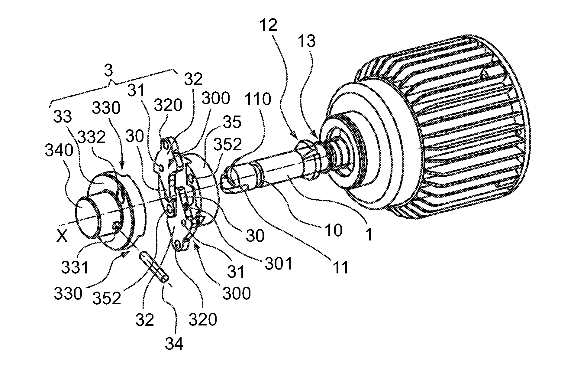
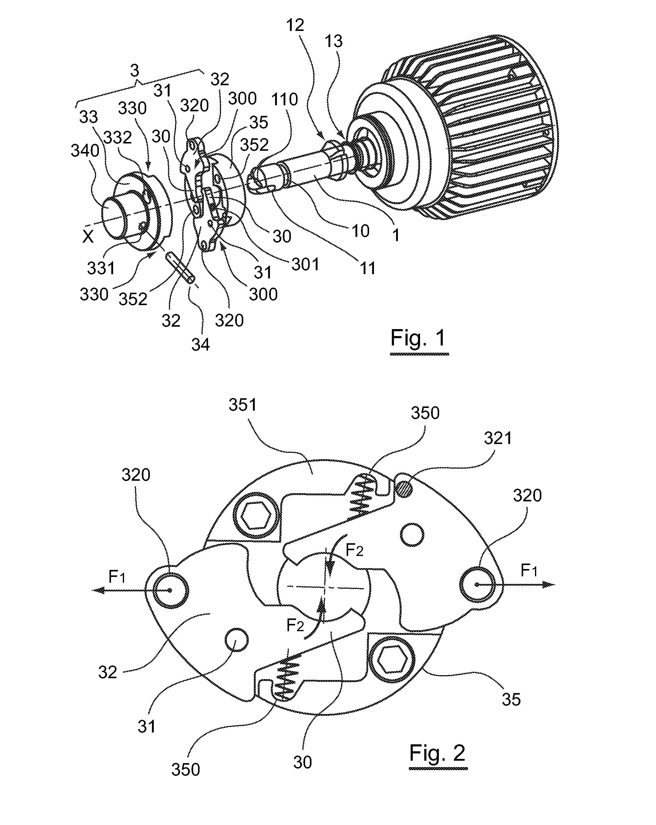
[0055]As indicated here above, the principle of an embodiment of the invention lies in the fact of associating, in a centrifuge, elements for the axial locking of the rotor on the drive shaft with a visual and / or tactile indicator providing a visual and / or tactile indication when the male element or elements of the axial locking device are in a position of cooperation with the female element of the drive shaft.

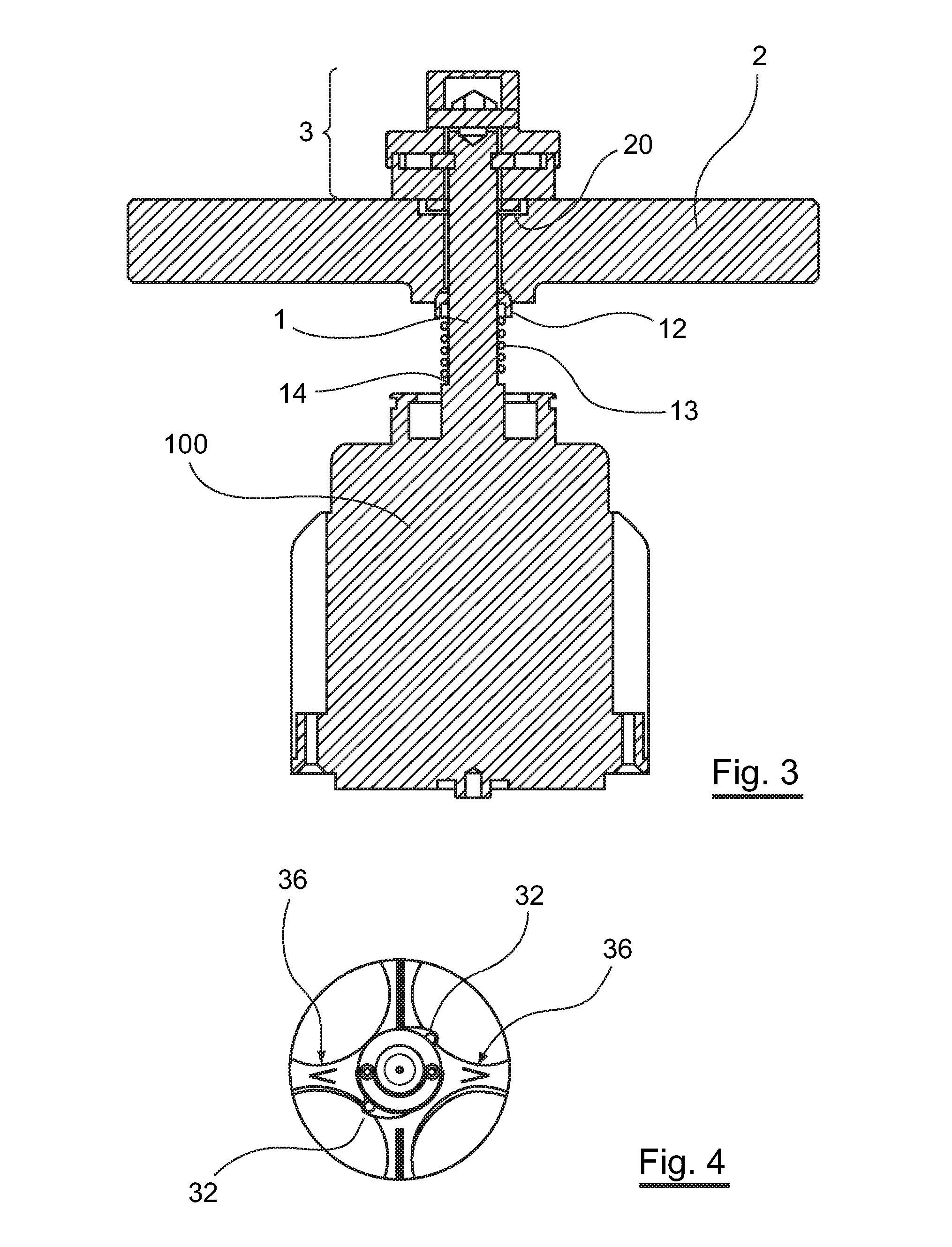
[0056]Referring to FIG. 3, a centrifuge according to an embodiment of the invention, in a manner known per se, comprises a vessel (not shown) incorporating:[0057]a motor unit 100 connected to a drive shaft 1;[0058]a rotor 2 mounted removably on the drive shaft 1, in a mounting position for which the drive shaft and the rotor are rotationally coupled;[0059]a device 3 providing for an axial locking of the rotor to the drive shaft.

[0060]According to the present embodiment, the axial locking of the rotor to the drive shaft is obtained by the implementing of:[0061]an annular groove...


PUM


Abstract

A centrifuge is provided, which includes a drive shaft and a rotor intended to be removably mounted on the drive shaft in a mounting position. The drive shaft and the rotor are rotatably linked. The centrifuge also includes an axial locking device, which locks the rotor on the drive shaft and includes at least one male element supported by the rotor, resiliently biased and able to engage with a female element on the drive shaft. The male element(s) is(are) linked to a visual and/or tactile indicator, providing a visual and/or tactile indication of the engagement of the male element(s) with the female element.

Description

CROSS-REFERENCE TO RELATED APPLICATIONS[0001]This Application is a Section 371 National Stage Application of International Application No. PCT / EP2010 / 0066821, filed Nov. 4, 2010, which is incorporated by reference in its entirety and published as WO 2011 / 054906 on May 12, 2011, not in English.STATEMENT REGARDING FEDERALLY SPONSORED RESEARCH OR DEVELOPMENT[0002]None.THE NAMES OF PARTIES TO A JOINT RESEARCH AGREEMENT[0003]None.FIELD OF THE DISCLOSURE[0004]The field of the disclosure is that of the designing and manufacture of centrifugation equipment. More specifically, the disclosure pertains to centrifuges used in the fields of biology to centrifuge the products contained in receptacles placed in housings made in the rotor or carried by the rotor.BACKGROUND OF THE DISCLOSURE[0005]Classically, the centrifuge comprises:[0006]a drive shaft,[0007]a rotor designed to be mounted removably on the drive shaft in a mounting position for which the drive shaft and the rotor are coupled in rota...

Claims


Application Information

Patent Timeline
Patent Type & Authority Applications(United States)
IPC IPC(8): B04B9/00
CPCB04B9/08B04B2009/085B04B9/00F16D1/116F16D2300/18F16D1/06
Inventor LETOURNEUR, JEAN-CLAUDELE GUYADER, PHILIPPELAMBERT, ROLANDFONDIN, JEAN-LOUIS
Owner BMS INT
Why Eureka
Try Eureka