Method of correcting a lateral trajectory on approach as a function of the energy to be reabsorbed

a technology of lateral trajectory and energy to be reabsorbed, applied in the direction of vehicle position/course/altitude control, process and machine control, instruments, etc., can solve the problem of not being compatible with the aircraft's performance, the determination of the three-dimensional trajectory of the aircraft is subject to additional constraints, and the “forward” calculation fails to link up

Active Publication Date: 2013-09-12
THALES SA
View PDF13 Cites 16 Cited by
  • Summary
  • Abstract
  • Description
  • Claims
  • Application Information

AI Technical Summary

Benefits of technology

The invention allows for processing ground speed and altitude constraints using the energy of the aircraft. This can be done using either an energy approach or a mechanical approach based on the laws of dynamics. The technical effects include improved efficiency and more accurate control of the aircraft's speed and height.

Problems solved by technology

During a landing runway approach phase, the determination of the three-dimensional trajectory of the aircraft is subject to additional constraints.
A problem with the determination of the theoretical approach trajectory is that it is not necessarily compatible with the aircraft's performance.
Numerically, the “forward” calculation does not succeed in linking up with the “backward” calculation, at the runway.
However, this visual information does not make it possible to determine whether or not it is possible to correct the ground speed and the altitude during the final approach so as to reach the runway threshold with the required conditions.
Thus, the current solutions merely provide an item of information according to which the energy of the aircraft is incompatible with the maximum permissible energy for the landing, and do not propose any lateral or vertical trajectory correction.

Method used


Image

  • Method of correcting a lateral trajectory on approach as a function of the energy to be reabsorbed
  • Method of correcting a lateral trajectory on approach as a function of the energy to be reabsorbed
  • Method of correcting a lateral trajectory on approach as a function of the energy to be reabsorbed

Examples


Embodiment Construction

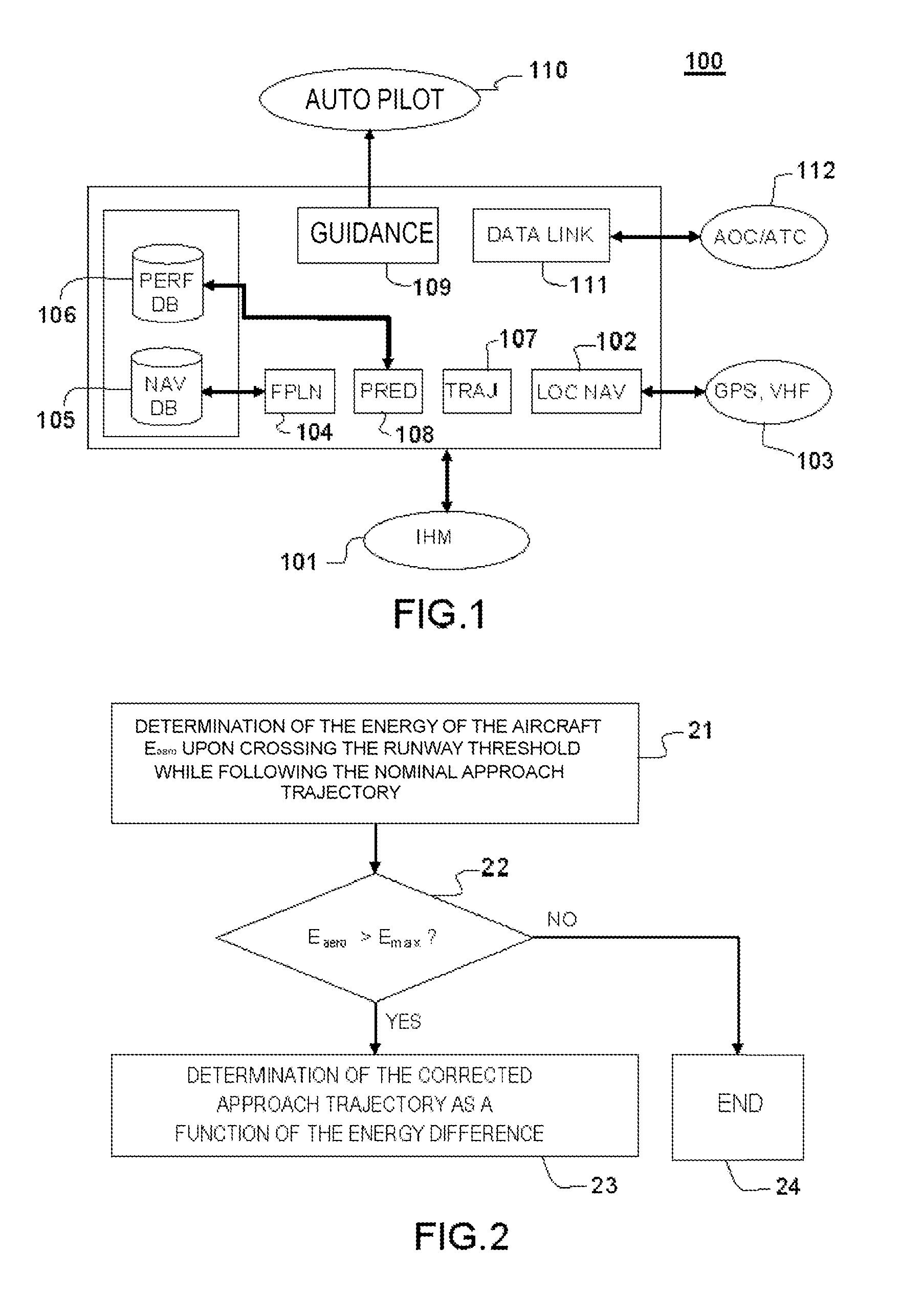
[0042]FIG. 1 is a functional representation of a flight management system for an aircraft. A flight management system is commonly abbreviated to FMS. The FMS 100 represented in FIG. 1 comprises a man-machine interface 101 and modules fulfilling the various functions described in the ARINC 702 standard entitled “Advanced Flight Management Computer System”. The man-machine interface 101 comprises for example a keyboard and a display screen, or quite simply a tactile display screen. A navigation module 102, named “LOC NAV”, makes it possible to perform optimal location of the aircraft as a function of geolocation means 103, for example a satellite (GPS or GALILEO) location system, VHF radionavigation beacons, or inertial platforms. A module 104 for determining flight plans, named “FPLN”, makes it possible to input the geographical elements constituting the skeleton of the route to be followed, such as the points imposed by the departure and arrival procedures, the waypoints, and the ai...


PUM


Abstract

In the field of the calculation of the approach trajectory of an aircraft, and relating to a method for determining a corrected lateral approach trajectory as a function of the energy to be reabsorbed before the landing, and also to a flight management system making it possible to determine the corrected lateral trajectory, a method comprises: determining an energy of the aircraft Eaero upon crossing the runway threshold on the basis of a predetermined approach trajectory and of a current state of the aircraft, said state comprising at least one current altitude, a current ground speed and a mass of the aircraft; comparing the energy Eaero with a predetermined maximum energy Emax, and when the energy Eaero is greater than the energy Emax, determining the corrected lateral approach trajectory as a function of the difference between the energy of the aircraft Eaero and the maximum energy Emax.

Description

CROSS-REFERENCE TO RELATED APPLICATION[0001]This application claims priority to foreign French patent application No. FR 1200702, filed on Mar. 8, 2012, the disclosure of which is incorporated by reference in its entirety.FIELD OF THE INVENTION[0002]The invention lies in the field of the calculation of the approach trajectory of an aircraft. It relates to a method for determining a corrected lateral approach trajectory as a function of the energy to be reabsorbed. The invention also relates to a flight management system making it possible to determine the corrected lateral trajectory.BACKGROUND[0003]Today, most civil aircraft are equipped with a flight management system, commonly abbreviated FMS. An FMS consists of various functional components which allow notably the crew of the aircraft to define a flight plan on the basis of departure and arrival points and of a navigation database. A flight plan furthermore comprises a chronological sequence of waypoints described by their three...

Claims


Application Information

Patent Timeline
IPC IPC(8): G05D1/06
CPCG05D1/101G05D1/0676
Inventor DEWAS, EMMANUELSAVARIT, VINCENTCOULMEAU, FRANCOIS
Owner THALES SA
Why Eureka
Try Eureka