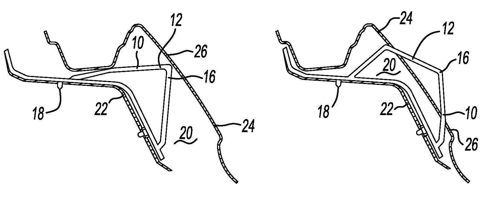
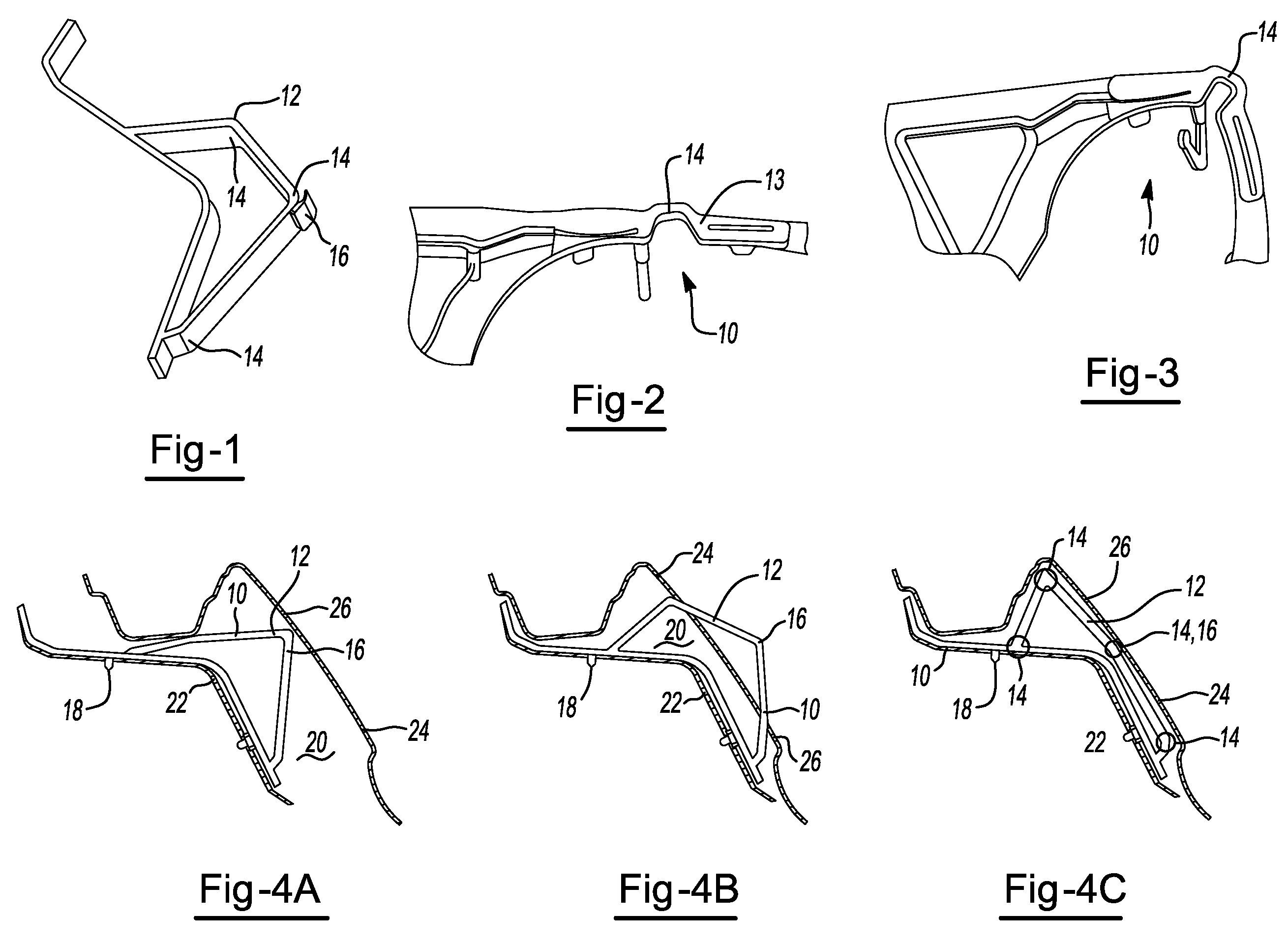
Load actuated baffle

Inactive Publication Date: 2013-09-19
ZEPHYROS INC
View PDF13 Cites 12 Cited by
  • Summary
  • Abstract
  • Description
  • Claims
  • Application Information

AI Technical Summary

Benefits of technology

[0004]During the step of activating, the foam may bond to each of the first and second substrates. The insert and expandable material may provide baffling for the cavity. The insert and expandable material may provide structural reinforcement for the cavity. The method may be free of any step where the pre-formed insert returns to the first pre-installation configuration after attachment of the second substrate. One or more of the plurality of living hinges may be substantially free of any metallic component. One of the first substrate or second substrate may be in line contact with the contact surface. One of the first substrate or second substrate may be in point contact with the contact surface. One of the first substrate or second substrate may be in area contact with the contact surface. The contact surface may be a structure that is sufficiently resilient that it will resist read-through through the outer surface of the second substrate subsequent to assembly. The pre-formed insert may include at least hinges. The carrier may be defined to include a loop. At least one living hinge may open and at least one living hinge may close. The pre-installation configuration may enable clearance for installation of the second substrate so that the second substrate contacts the contact surface prior to contacting any other portion of the insert. A single point of contact may cause multiple degrees of movement of the plurality of living hinges. The insert may form into the second installed configuration as a result of the first and second surface being brought into contact with one another. The plurality of living hinges may be free of hinges that extend beyond 180°.

Problems solved by technology

As a result, efforts have been made to produce parts that are movable, any such parts are formed to move but fail to return to the desired location within a cavity.

Method used


Image

  • Load actuated baffle
  • Load actuated baffle

Examples


Embodiment Construction

[0012]The explanations an illustrations presented herein are intended to acquaint others skilled in the art with the invention, its principles, and its practical application. Those skilled in the art may adapt and apply the invention in its numerous forms, as may be best suited to the requirements of a particular use. Accordingly, the specific embodiments of the present invention as set forth are not intended as being exhaustive or limiting of the teachings. The scope of the teachings should, therefore, be determined not with reference to the above description, but should instead be determined with reference to the appended claims, along with the full scope of equivalents to which such claims are entitled. The disclosures of all articles and references, including patent applications and publications, are incorporated by reference for all purposes. Other combinations are also possible as will be gleaned from the following claims, which are also hereby incorporated by reference into t...


PUM

PropertyMeasurementUnit
temperaturesaaaaaaaaaa
elastic deformationaaaaaaaaaa
frictionaaaaaaaaaa

Abstract

A device for reinforcing, baffling or sealing a vehicle structure that includes hinge structures for allowing the member to be moveable within a cavity and free of any spring effect during movement.

Description

TECHNICAL FIELD[0001]The present invention relates generally to a baffling, sealing, or reinforcement member that includes hinge structure for allowing the member to be moveable within a cavity and free of any spring effect during movement.BACKGROUND[0002]The transportation industry continues to require methods of baffling, reinforcement and sealing that provide improved functionality while simultaneously providing reduced weight and cost. Often, the assemblies utilized will be required to move during the installation and manufacturing process. As a result, efforts have been made to produce parts that are movable, any such parts are formed to move but fail to return to the desired location within a cavity. There is thus a need in the art of sealing for parts that are both movable and yet formed to re-locate to a specific location after movement.SUMMARY OF THE INVENTION[0003]The present teachings meet the aforementioned inert by providing in a first aspect, a method for baffling, rei...

Claims


Application Information

Patent Timeline
Patent Type & Authority Applications(United States)
IPC IPC(8): B60R13/00B32B37/12
CPCB29C44/188B32B37/12B22F7/006B62D29/002B22F3/004B60R13/00
Inventor SHANTZ, JEFFREY THOMASMANGIAPANE, ALEXANDER GABRIELRICHARDSON, HENRY E.
Owner ZEPHYROS INC
Why Eureka
Try Eureka