Extendable and retractable utility line system

a technology of utility lines and hoses, applied in the field of hoses for selective extending and retracting utility lines, can solve the problems of unsightly appearance of utility lines, potential damage and entanglement, and cinch-less or pinch-less braking structure, and achieve the effect of effectively braking the utility lin

Inactive Publication Date: 2006-07-18
JOHNSTONE CHARLES R
View PDF25 Cites 9 Cited by
  • Summary
  • Abstract
  • Description
  • Claims
  • Application Information

AI Technical Summary

Benefits of technology

[0017]Each pulley-receiving wall comprises an inner wall surface, an outer wall surface, and a pulley-receiving groove situated intermediate the inner wall and outer wall surfaces. The pulley-receiving grooves together cooperatively form the pulley-receiving track. The pulley-receiving track comprises an inferior track path, a superior track region, and a pulley guide junction intermediate the inferior track path and the superior track region. The superior track region essentially comprises a closed path comprising an anterior track path or ascension path, a posterior track path or descension path and superior path track with transitional braking means or an extended brake stop intermediate the anterior track path and the posterior track path. The extended-state rest stop effectively provides cinch-less or pinch-less braking structure so as to effectively brake the utility line when it is in extended utility line use.

Problems solved by technology

It has been noted that when an effective dental utility line storage system (that enables the user to selectively extend a line for use and selectively retract a line for storage) is not employed in a dental practice setting, the dental utility lines often become entangled with one another or damaged by everyday office behavior, such as by being trampled under foot or by rolling chairs and the like.
Added to the potential for damage and entanglement is the rather unsightly appearance of utility lines.
From a thorough inspection of the prior art, it will be seen, however, that none of the prior art teach a uniquely configured traveling pulley assembly track comprising an ascension path for utility line extensions and a separate and distinct descension path for utility line retractions.
Further, it is noted that prior art braking systems employing line-cinching or line-pinching means for braking the utility line are deficient for various reasons.
In this regard, it has been noted that cinch or pinch-type braking means, which attempt to hold utility lines in an extended state for utility line use often fail to properly grab or hold the utility line in place for utility line use.
These utility lines often rotate about the axis extending therethrough and thus means for cinching or pinching the line in place often fail to properly make sufficient frictional contact with the utility line for holding the same in place.
Further, these systems may compromise the effectiveness of the utility line by kinking the line or by damaging the line from repeated pinched engagement.
While the '874 Patent teaches braking means that do not comprise line-cinching or line-pinching means for braking a utility line, the '874 Patent does not teach a positive tracking system with transitional lock or transitional brake means.
From a review of the above-referenced patents and other prior art generally known to exist, it will be seen that the prior art does not teach a positive tracking system, comprising a closed path with transitional braking means along the closed path.
It will be further seen that the prior art does not teach a selectively extendable and selectively retractable utility line system comprising non-frictional braking means.

Method used


Image

  • Extendable and retractable utility line system
  • Extendable and retractable utility line system
  • Extendable and retractable utility line system

Examples


Embodiment Construction

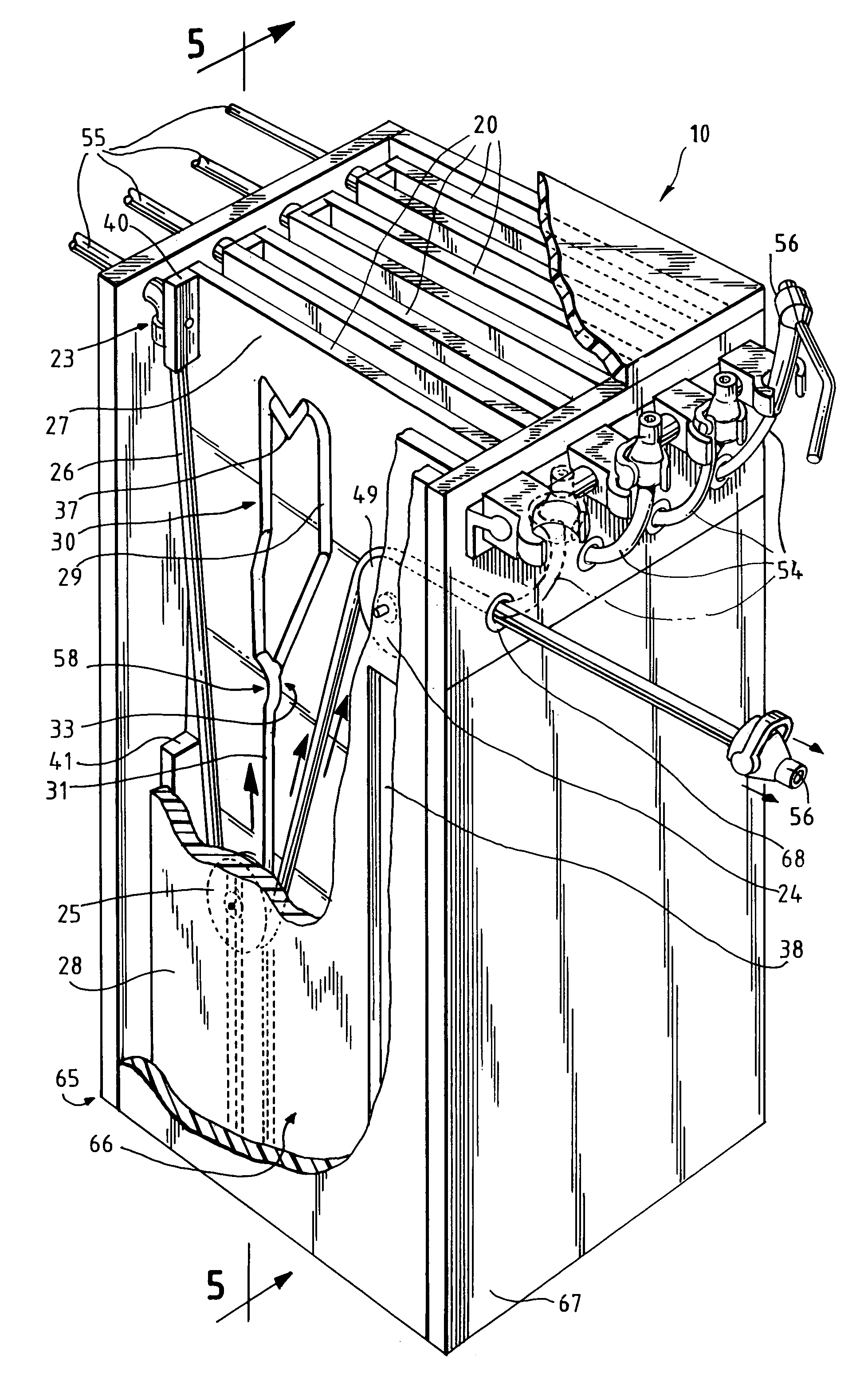
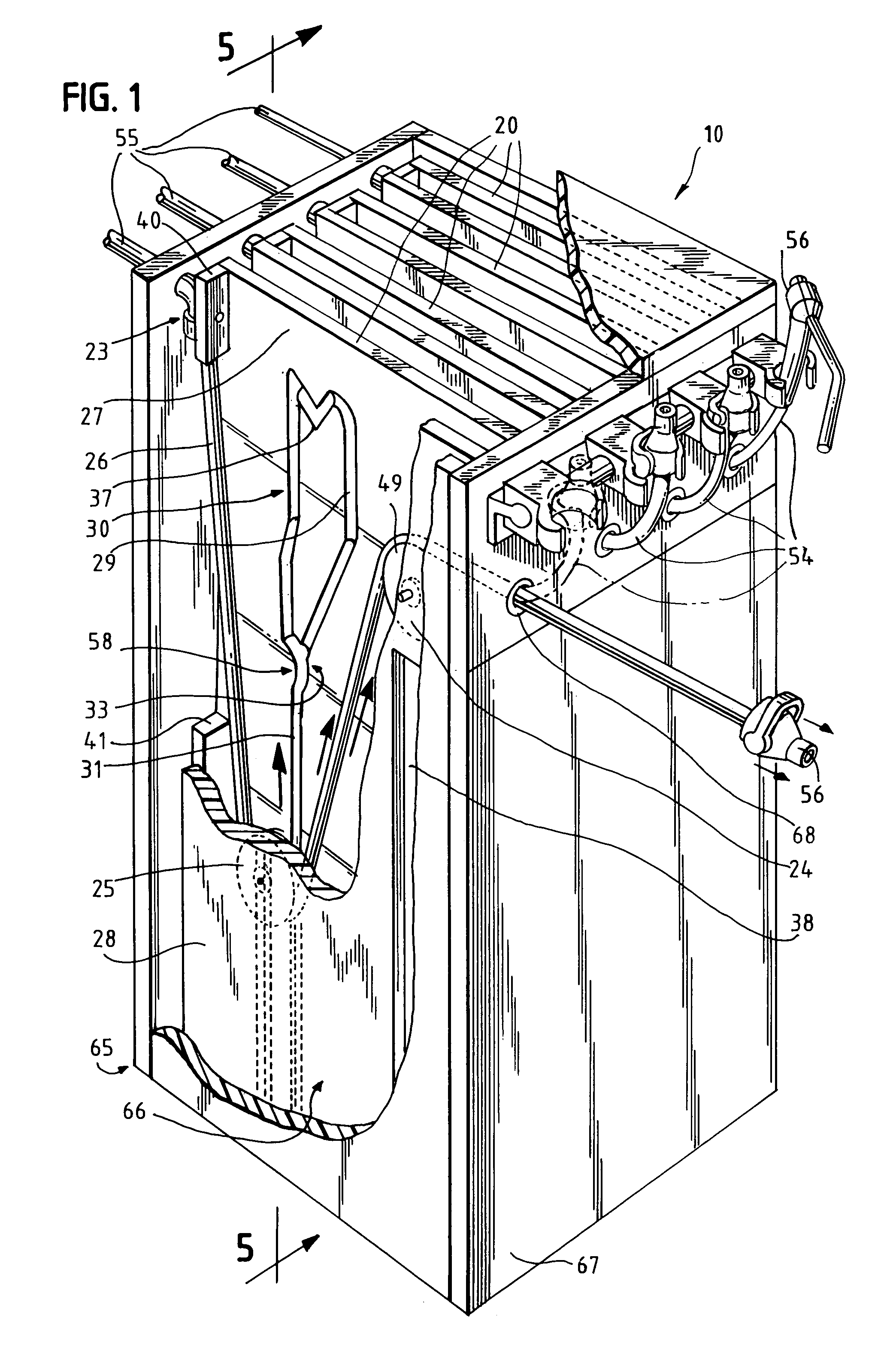
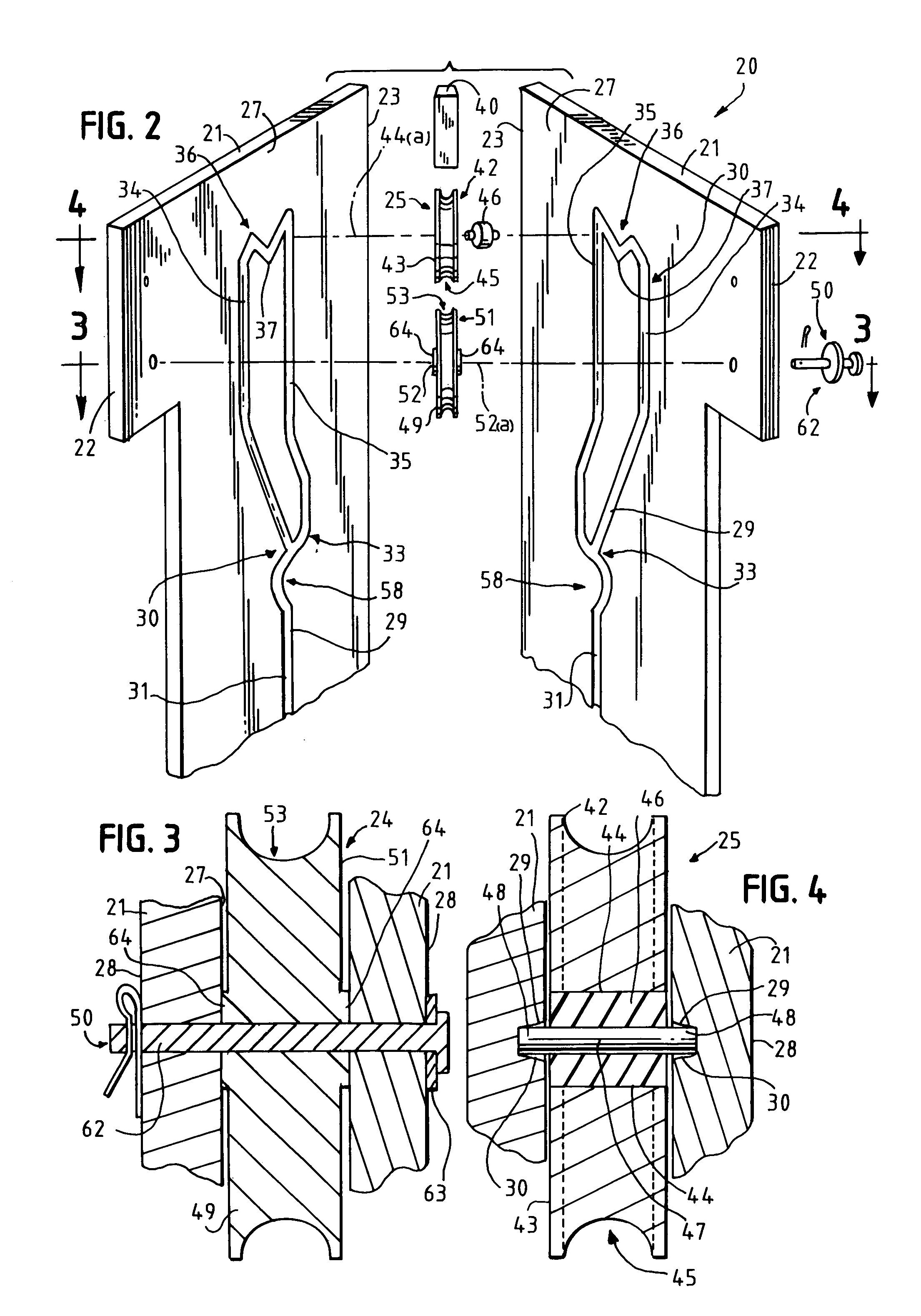
[0040]Referring now to the drawings, the preferred embodiment of the present invention concerns a utility line extension and retraction system or utility line extension and retraction cassette assembly for enabling users thereof to selectively extend a utility line for utility line use and retract the utility line for utility line storage. The utility line extension and retraction system 10 is generally illustrated and referenced in FIG. 1. It will be seen from an inspection of FIG. 1 that utility line extension and retraction system 10 essentially comprises a plurality of utility line cassettes 20 or cassette assemblies, which utility line cassette 20 or cassette assembly has further been illustrated and referenced in FIGS. 2, and 5–10. Each utility line cassette 20 preferably comprises two laterally-spaced, pulley-receiving walls 21 as illustrated and referenced in FIGS. 2–10; spacer means intermediate the pulley-receiving walls; an anterior line outlet end 22 as illustrated and r...


PUM


Abstract

The present invention provides a utility line extension and retraction system for enabling users thereof to selectively extend a utility line for utility line use and retract the utility line for utility line storage. The utility line extension and retraction system essentially comprises a plurality of utility line cassettes. Each utility line cassette essentially comprises two laterally-spaced, pulley-receiving walls, an anterior line outlet end, a posterior line inlet end, a stationary pulley assembly adjacent the anterior line outlet end; a traveling pulley assembly intermediate the anterior line outlet end and the posterior line inlet end, and a utility line extending from the posterior line inlet end to the anterior line outlet end, which line imparts motion to the traveling pulley assembly. The traveling pulley assembly travels along a closed path comprising an ascension path, a descension path, and an extended-state rest stop intermediate the ascension and descension paths.

Description

BACKGROUND OF THE INVENTION[0001]1. Field of the Invention[0002]The present invention generally relates to an apparatus for selectively extending and retracting a utility line, hose, or the like. More particularly, the present invention relates to an apparatus for selectively extending a dental utility line for utility line use and selectively retracting a dental utility line for utility line storage.[0003]2. Description of the Prior Art[0004]The prior art is replete with examples of apparatus and systems for enabling users to selectively extend and retract a utility line, hose, or cord. The dental industry, in particular, requires utility lines for the actuated use of a variety of dental instruments and appliances and thus has been offered a variety of means for selectively extending and selectively retracting utility lines in the office. It has been noted that when an effective dental utility line storage system (that enables the user to selectively extend a line for use and selec...

Claims


Application Information

Patent Timeline
Patent Type & Authority Patents(United States)
IPC IPC(8): A61C13/38A61G15/00A61G15/18
CPCA61G15/18Y10T137/6921
Inventor JOHNSTONE, CHARLES R.
Owner JOHNSTONE CHARLES R
Why Eureka
Try Eureka