Refuse container holder system

a technology for storing containers and containers, applied in the field of storing containers, can solve the problems of inability to inability to meet the needs of users, so as to facilitate maintenance, improve appearance, and hold and physically stabilize containers

Inactive Publication Date: 2008-10-07
HABIB JOSEPH M
View PDF21 Cites 8 Cited by
  • Summary
  • Abstract
  • Description
  • Claims
  • Application Information

AI Technical Summary

Benefits of technology

[0011]This invention is a device for holding and physically stabilizing refuse containers, especially when those refuse containers are positioned at the curbside in front of the residence. A device includes a vertical element, and especially a vertical element rendered stationary by being buried in the ground. It could also be stabilized by being mounted on a stable base that could be movable with effort but not by the normal wind. The vertical element includes one or more upwardly directed hooks that are capable of engaging a handle on a refuse container so that the refuse container cannot be overturned or moved by the wind but can easily be lifted off the hook by a refuse collector. Each hook is capable of engaging a separate refuse container or several hooks could be arranged in a linear manner to more stably engage an elongated handle on the refuse container. The device might also include a horizontal element parallel to and adjacent the ground upon which the refuse containers can sit.
[0012]This invention may include a plastic casing to provide structure, improve appearance, and ease maintenance. This invention may also include a cooperation between the horizontal element and grooves in the bottom of the containers. The grooves engage the upper surface of the horizontal elements to stabilize the container on the holder.

Problems solved by technology

Because refuse containers tend to be relatively large volume, so that they can hold significant refuse, but relatively light in weight, so that they are relatively easy to move from the residence to the curbside and relatively easy to empty into the refuse collection vehicle, the containers are inherently physically unstable.
When the refuse containers are standing by the curbside filled with refuse, they are often disturbed by the wind or roaming animals and are knocked over, spilling the refuse in allowing it to be scattered around the ground.
Furthermore, after the refuse has been removed from the containers, the wind frequently most the containers down the sidewalks, and out into to the streets with the containers are sometimes crushed by vehicles and otherwise create dangerous obstacles to traffic.
Furthermore, the containers themselves are often lost as a travel around the neighborhood with the wind.

Method used


Image

  • Refuse container holder system
  • Refuse container holder system
  • Refuse container holder system

Examples


first embodiment

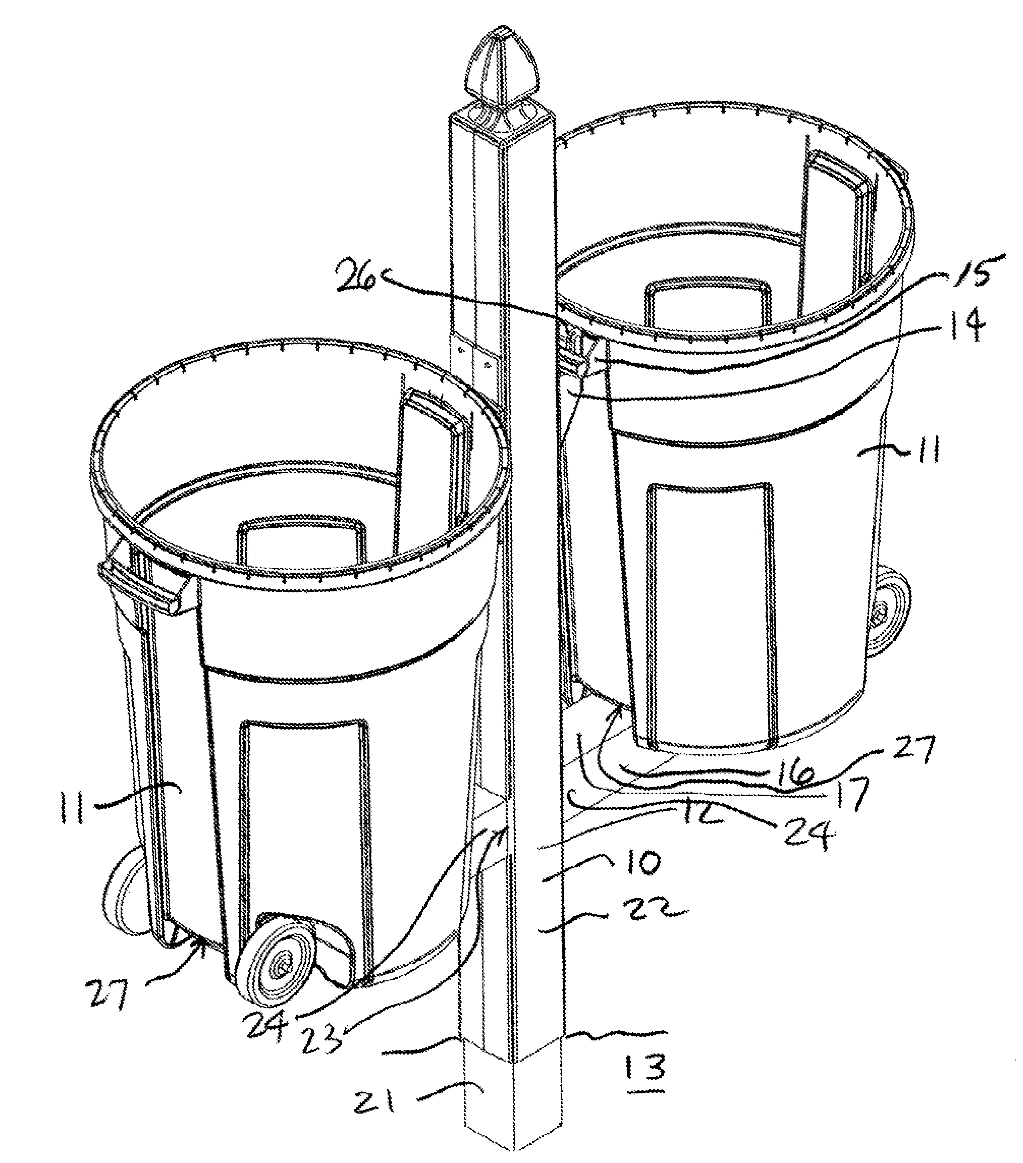
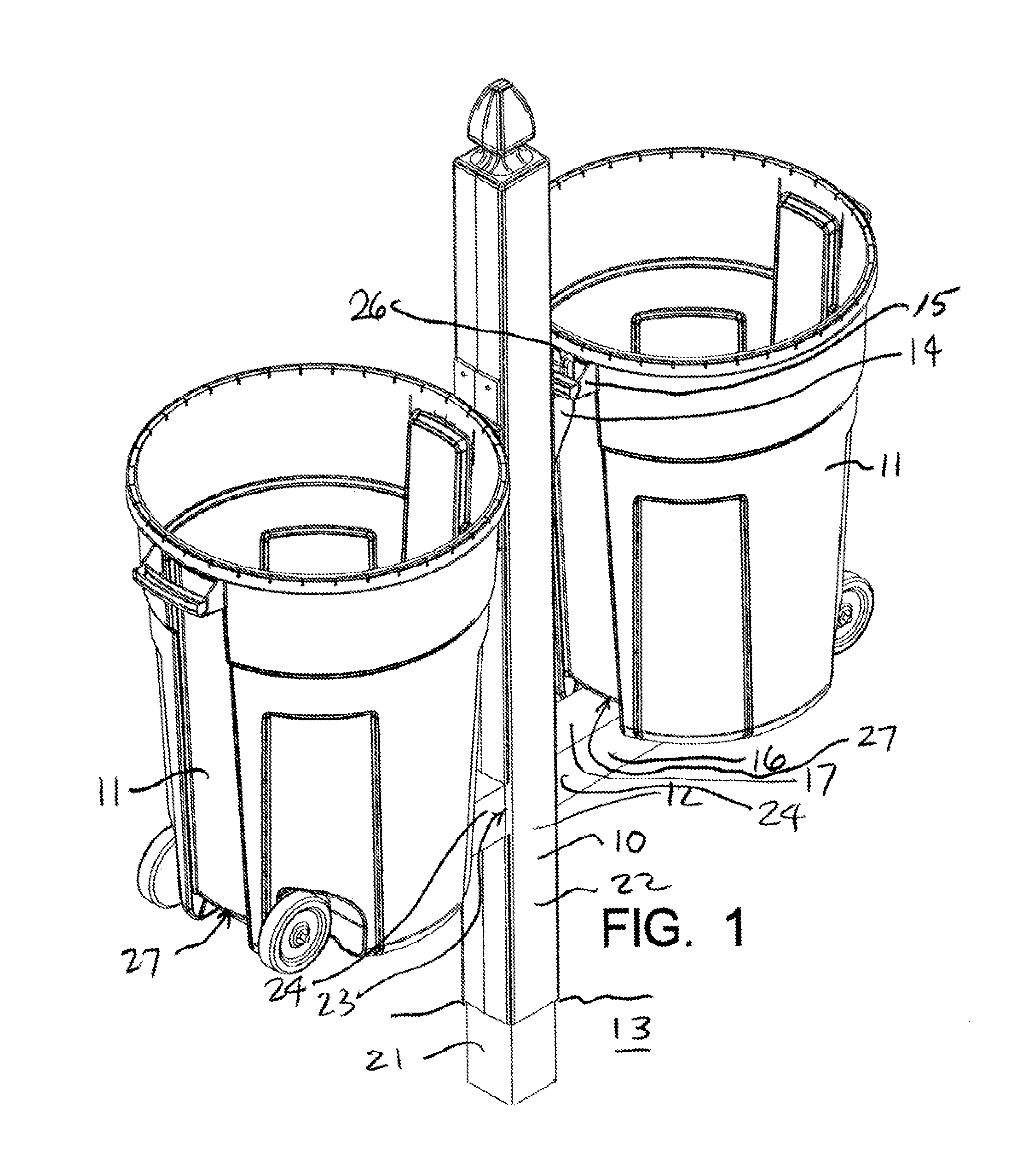
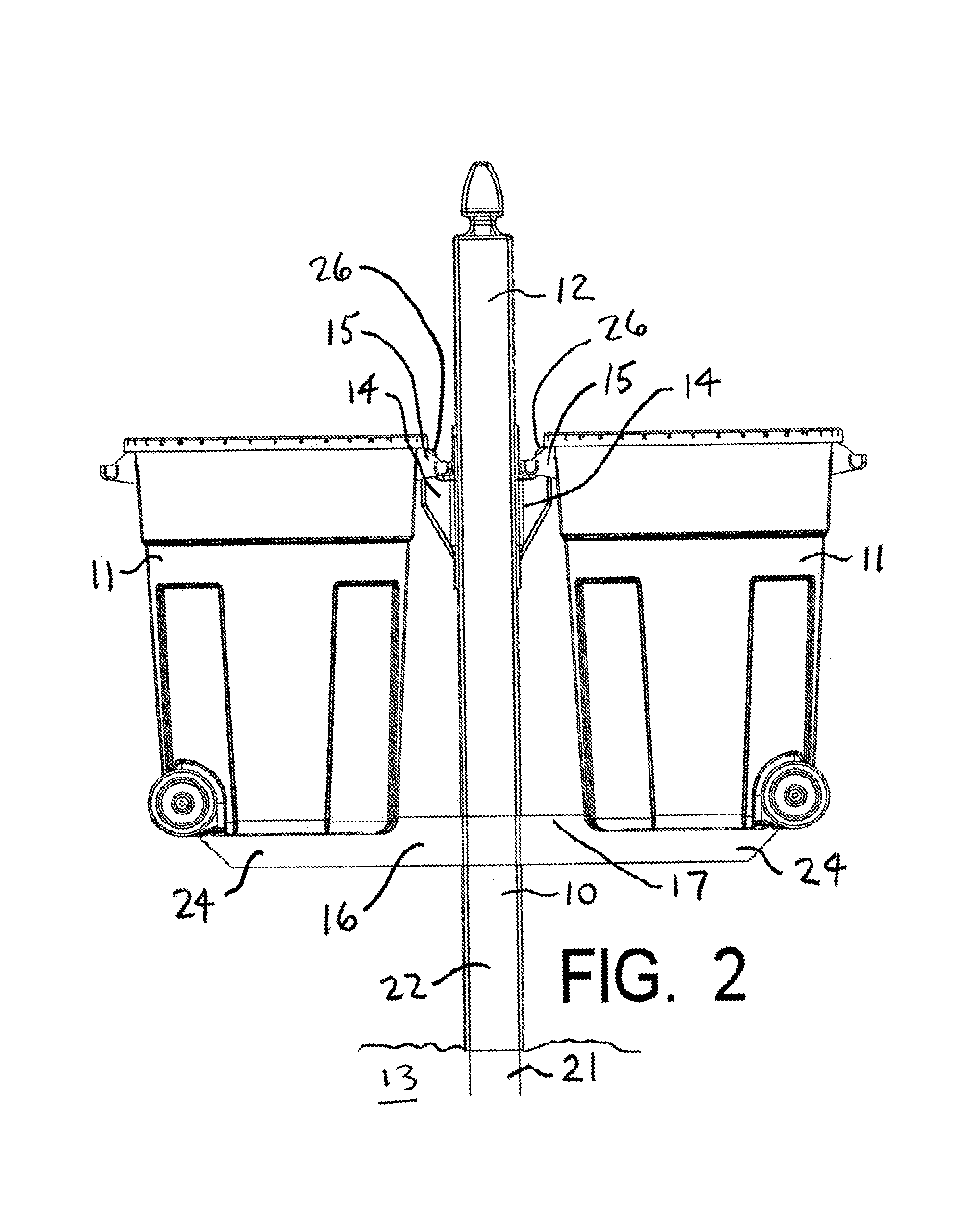
[0056]The installation of the first embodiment of the invention, as shown in FIG. 11, begins by installing a base element 21 into the ground 13, with an exposed end extending 8 to 12 inches above the ground surface. The base element would typically be 4 in. by 4 in. pressure treated wood.

[0057]As shown in FIG. 12, the vertical element casing 22, typically a hollow piece of plastic, would then be slipped over the exposed end of the base element 21. The vertical element casing is provided with diametrically opposed openings 23. The vertical element casing 22 and base element 21 would be positioned so that the lower edges of the openings 23 aligned with the upper surface of the base element 21. Then, the vertical element casing 22 would be fastened to the base element 21 with nails or screws to form the vertical element 12. The vertical element casing 22 would carry the upwardly facing hooks14.

[0058]As shown in FIG. 13, the horizontal element 16 is slid through the openings 23 in the v...

second embodiment

Alternative Second Embodiment

[0065]In any variation on the details of the second embodiment and its installation, as shown in FIG. 20, the base element 21a is installed just as had been shown in FIG. 15.

[0066]As shown in FIG. 21, the horizontal element 16a is then slipped over the base element 21a.

[0067]As shown in FIG. 22, the vertical element casing 22a including integral or preinstalled upwardly directed hooks 14a, is slipped over the base element 21a, and slid between the base element 21a and the horizontal element 16a. Then the vertical element casing 22a is fastened to the base element 21a using nails or screws. Then, the horizontal element 16a is positioned appropriately with respect to the upwardly directed hooks 14.

[0068]As shown in FIG. 23, a container 11 is placed on the horizontal element 16a with a handle 15 on the container 11 encircling the pin 26a of one of the upwardly directed hooks 14a on the horizontal element casing 22a. A groove 27 in the bottom of the contain...


PUM


Abstract

A refuse container holder for holding and physically stabilizing refuse containers, especially when those refuse containers are positioned at the curbside in front of the residence. A device includes a vertical element, that includes an upwardly directed hook that are capable of engaging a handle on a refuse container so that the refuse container cannot be overturned or moved by the wind but can easily be lifted off the hook by a refuse collector and may include a plastic casing. The device also includes a horizontal element. Each refuse container has a groove in its bottom surface adapted to engage the horizontal element and thereby enhance the stability of the refuse container on the horizontal element.

Description

CROSS-REFERENCE TO RELATED APPLICATIONS[0001]This application claims the benefit under 35 U.S.C. section 119(e) of U.S. Provisional Application No. 60 / 707,644 filed Aug. 12, 2005, which is hereby incorporated by reference.STATEMENT REGARDING FEDERALLY SPONSORED RESEARCH OR DEVELOPMENT[0002]This invention has been created without the sponsorship or funding of any federally sponsored research or development program.REFERENCE TO SEQUENCE LISTING, A TABLE, OR A COMPUTER PROGRAM LISTING COMPACT DISK APPENDIX[0003]Not applicableBACKGROUND OF THE INVENTION[0004]It has become very common for residential refuse to be placed in containers in front of the residence so that the refuse can be collected at the curbside by refuse collection organizations. Because refuse containers tend to be relatively large volume, so that they can hold significant refuse, but relatively light in weight, so that they are relatively easy to move from the residence to the curbside and relatively easy to empty into ...

Claims


Application Information

Patent Timeline
Patent Type & Authority Patents(United States)
IPC IPC(8): A47G23/02
CPCB65F1/141Y10S248/907
Inventor HABIB, JOSEPH M.
Owner HABIB JOSEPH M
Why Eureka
Try Eureka