

Lighting Control System, Lighting Control Method, and Storage Medium
a lighting control and control system technology, applied in lighting devices, instruments, light sources, etc., can solve problems such as complicated operation
- Summary
- Abstract
- Description
- Claims
- Application Information
AI Technical Summary
Benefits of technology
Problems solved by technology
Method used
Image

Examples
first embodiment
System Configuration
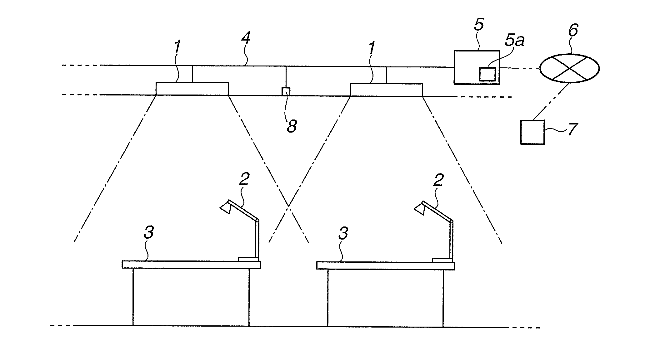
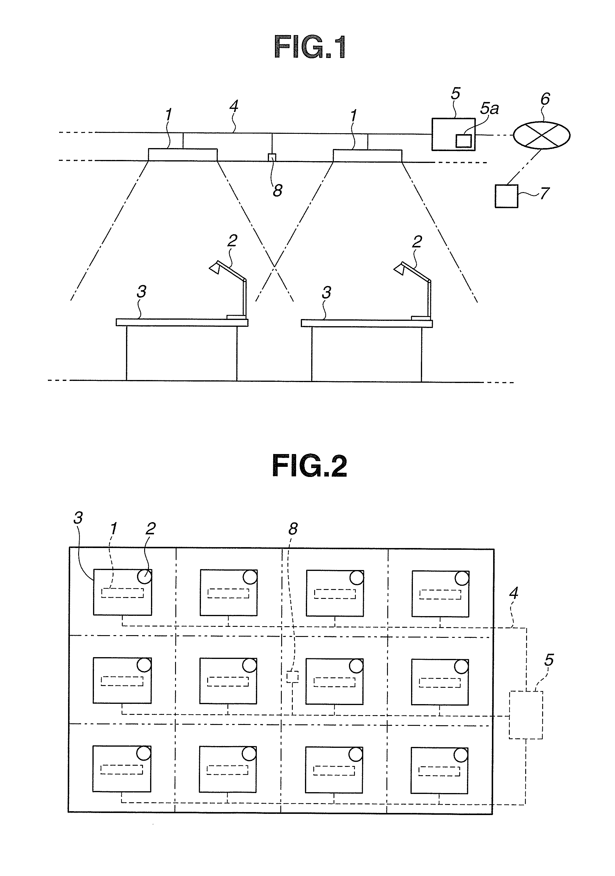
[0022]FIG. 1 is a diagram which describes a lighting control system according to the embodiment. FIG. 2 is a schematic plan view which describes an arrangement of an office in which lighting fixtures are arranged.
[0023]As illustrated in FIGS. 1 and 2, an office is divided into a plurality of areas, and a lighting fixture 1 for ambient lighting, and a lighting fixture 2 for task lighting are arranged in each area. The lighting fixture 1 for ambient lighting is attached to a ceiling plane, and the lighting fixture 2 for task lighting is provided at a desk 3 as a working table of a worker (hereinafter, referred to as user). That is, the lighting system in the office which is illustrated in FIGS. 1 and 2 is a Task-Ambient Lighting system.
[0024]In addition, here, as illustrated in FIG. 2, the office is equally divided into twelve areas, and one lighting fixture 1 for ambient lighting is installed with respect to one area, but, a method of dividing an area, and the num...
second embodiment
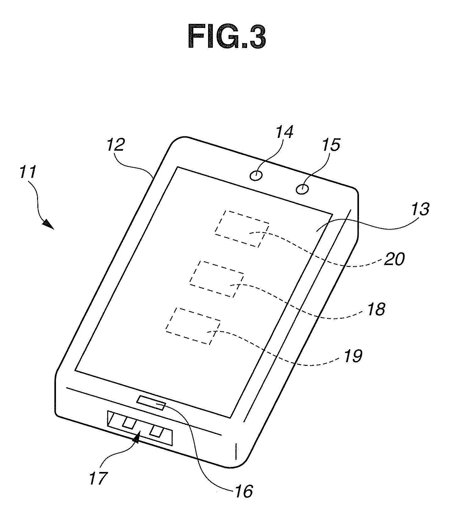
[0084]In the above described embodiment, the application for lighting control is started, and ended based on the illuminance of the illuminance sensor 15 which is provided in the smart phone 11, but, according to the embodiment, an execution, or starting of the application for lighting control is controlled based on a connection state between the smart phone 11 and a lighting fixture 2A for task lighting.
[0085]Since configurations of a lighting control system according to the embodiment are approximately the same as those in the lighting control system according to the first embodiment, configurations which are different from those in the lighting control system according to the first embodiment will be described, and the same constituent elements are given the same reference numerals, and descriptions thereof will be omitted.
[0086]FIG. 5 is a diagram which describes a state in which the lighting fixture 2A according to the embodiment and the smart phone 11 are connected using a con...
third embodiment
[0106]According to the second embodiment, the application for lighting control is started and ended based on the connection state between the smart phone 11 and the lighting fixture 2A for task lighting, but, according to the embodiment, the application for lighting control is executed, or started, and ended based on a reception of a predetermined signal by the smart phone 11.
[0107]Since configurations of a lighting control system according to the embodiment are approximately the same as those in the lighting control system according to the first and second embodiments, different configurations from the constituent elements of the lighting control systems in the first and second embodiments are described, the same constituent elements are given the same reference numerals, and descriptions thereof will be omitted.
[0108]FIG. 7 is a diagram which describes a lighting fixture 2B according to the embodiment on which the smart phone 11 can be mounted.
[0109]As illustrated in FIG. 7, a ped...
PUM
 Abstract
Description
Claims
Application Information