Eddy Current Inspection Device, Eddy Current Inspection Probe, and Eddy Current Inspection Method

a technology of eddy current inspection and inspection probe, which is applied in the direction of measurement devices, magnetic measurements, instruments, etc., can solve the problems of defect inspection in the deep parts of test objects, deficiency of magnetic field information acquired from the deep part of the test object, and high difficulty in inspection of defects in the deep parts of the test obj

Active Publication Date: 2013-09-19
HITACHI LTD
View PDF4 Cites 8 Cited by
  • Summary
  • Abstract
  • Description
  • Claims
  • Application Information

AI Technical Summary

Benefits of technology

[0020]According to the present invention, defects existing in deeper parts of test objects can be detected.

Problems solved by technology

However, defects in the test object can develop not only at the surface of the test object or in the vicinity of the surface but also in a deeper part.
However, there exists the problem that the magnetic field information acquired from the deep part of the test object is far more deficient compared to the magnetic field information from around the surface of the test object even at still lower frequencies.
Therefore, the defect inspection in deep parts of test objects has been extremely difficult.

Method used


Image

  • Eddy Current Inspection Device, Eddy Current Inspection Probe, and Eddy Current Inspection Method
  • Eddy Current Inspection Device, Eddy Current Inspection Probe, and Eddy Current Inspection Method
  • Eddy Current Inspection Device, Eddy Current Inspection Probe, and Eddy Current Inspection Method

Examples


first embodiment

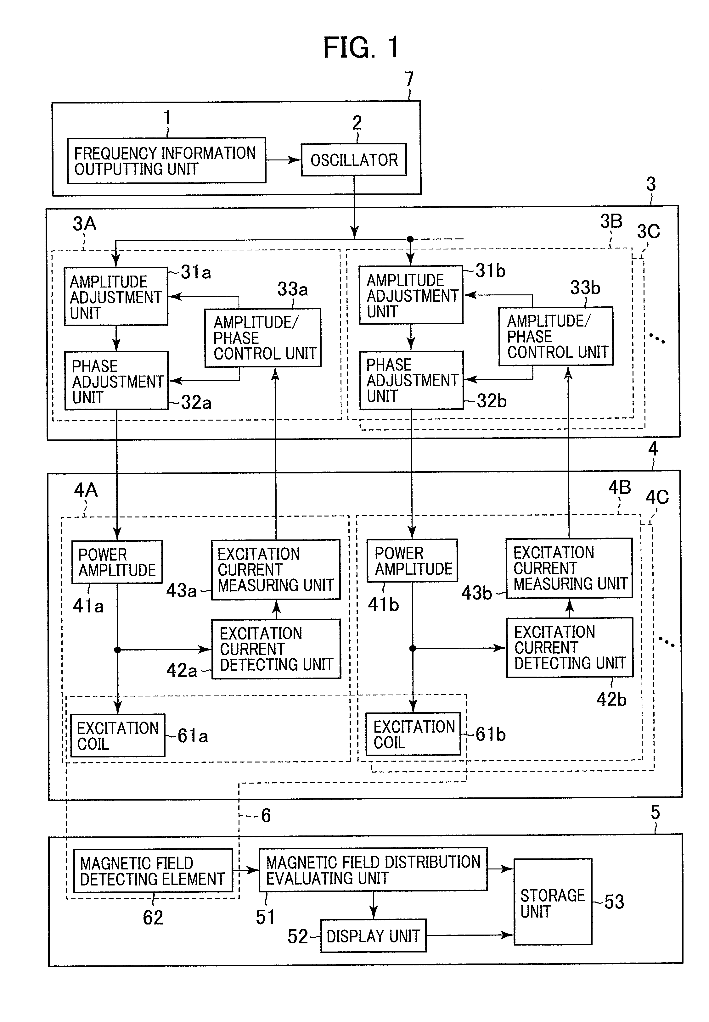
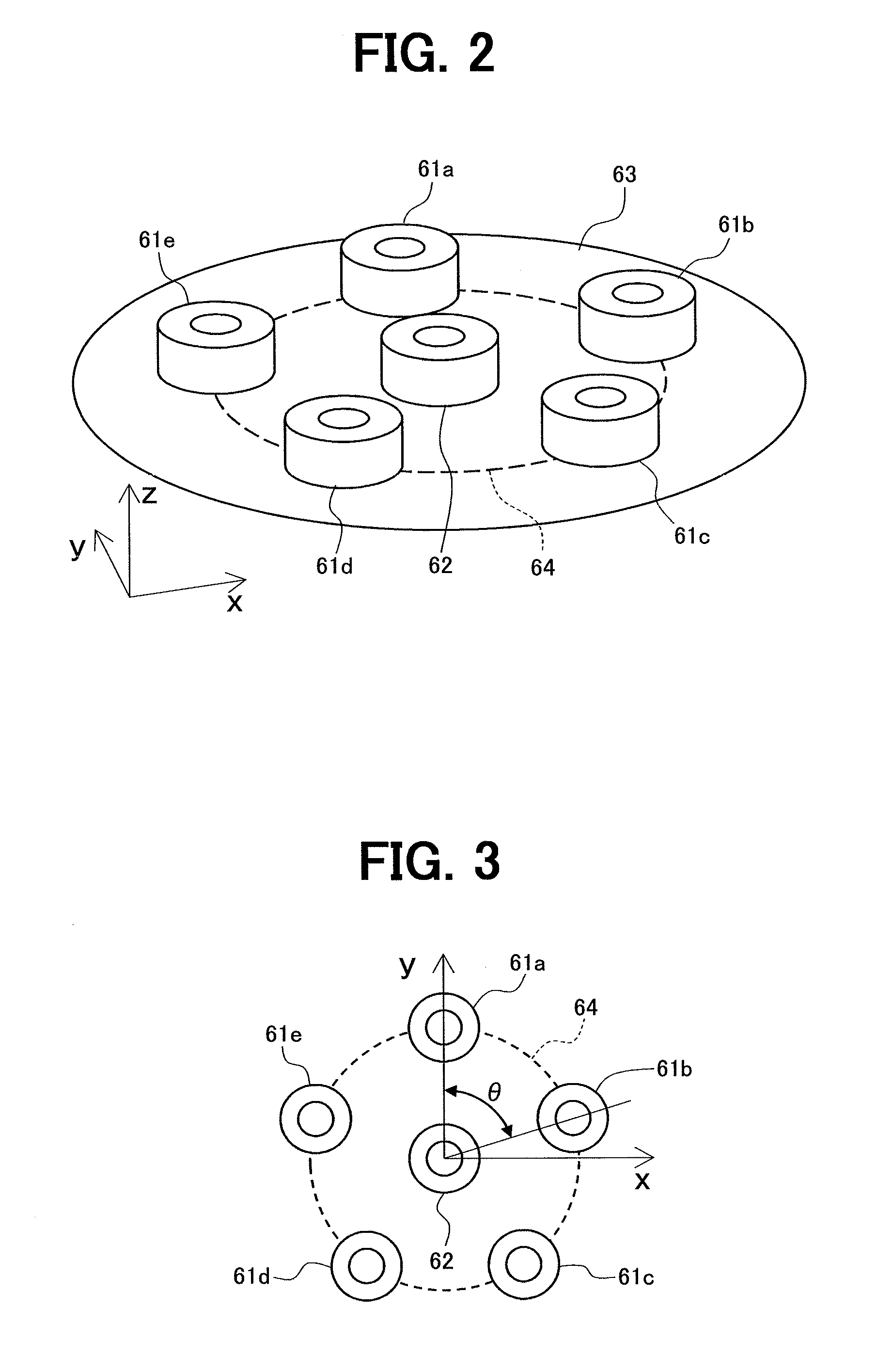
[0046]FIG. 1 is a functional block diagram showing the outline of the overall configuration of an eddy current inspection device in accordance with the first embodiment of the present invention. FIGS. 2 and 3 are a perspective view and a plan view schematically showing the arrangement of excitation coils and a detection coil in an eddy current inspection probe of the eddy current inspection device.

[0047]Referring to FIG. 1, the eddy current inspection device of this embodiment comprises a frequency information outputting unit 1, a fundamental signal generating section 7, an excitation signal generating section 3, a magnetic field generating section 4 and a detection section 5. The frequency information outputting unit 1 generates and outputs information on the frequency of a fundamental signal. The fundamental signal generating section 7 has an oscillator 2 for generating and outputting the fundamental signal (as the foundation for generating excitation currents to be used for the i...

second embodiment

[0087]A second embodiment of the present invention will be described below with reference to figures.

[0088]In this embodiment, the excitation signal generating section in the first embodiment is configured in multistage structure.

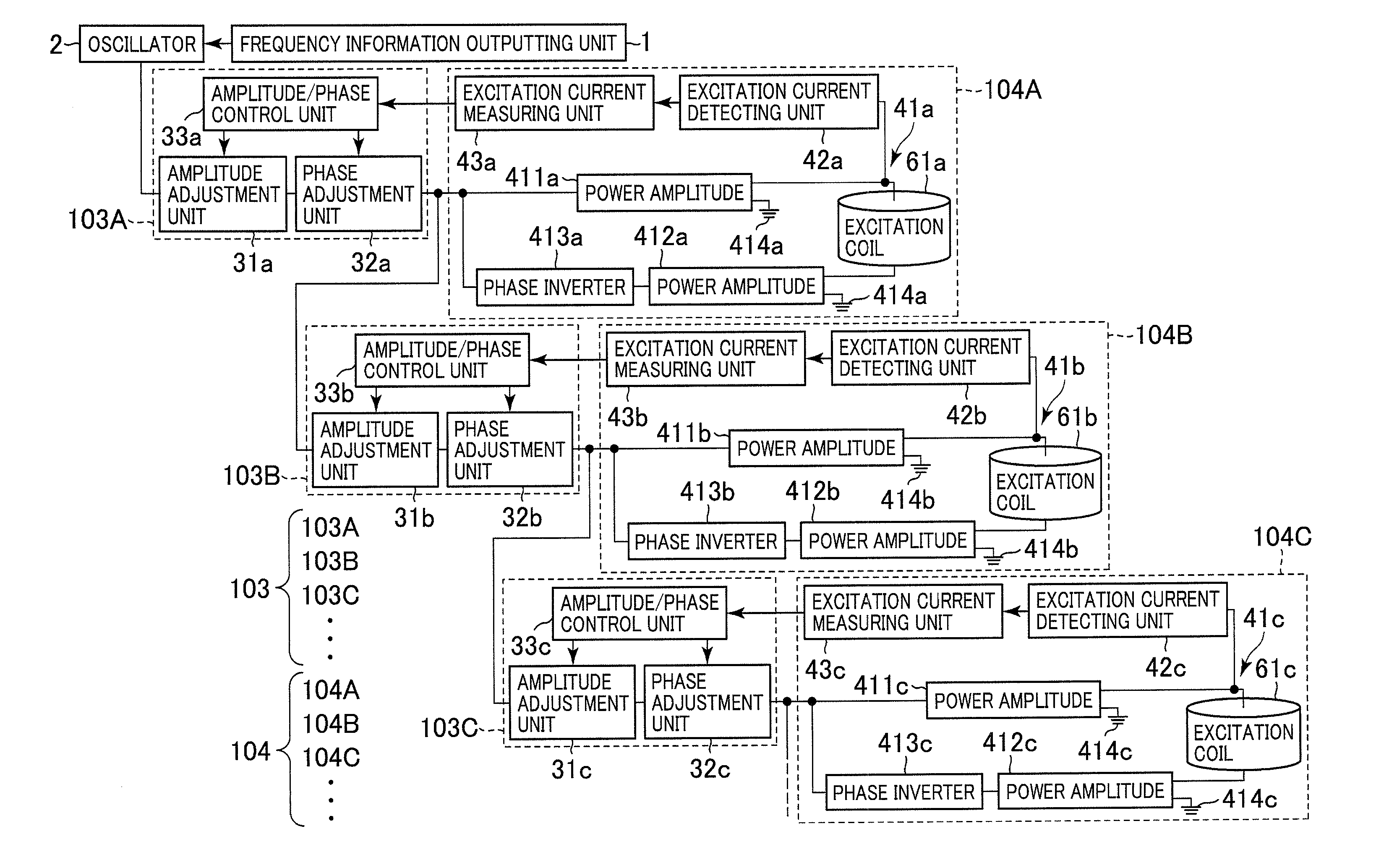
[0089]FIG. 23 is a functional block diagram showing the outline of the excitation signal generating section, the magnetic field generating section and the excitation coils of the eddy current inspection device in accordance with this embodiment. Illustration and explanation of components corresponding to the detection section in the first embodiment are omitted for brevity. Components in FIG. 23 equivalent to those in the first embodiment are assigned the same reference characters as in the first embodiment and repeated explanation thereof is omitted here.

[0090]As partially shown in FIG. 23, the eddy current inspection device of this embodiment comprises a frequency information outputting unit 1, a fundamental signal generating section 7, excitation signal ...

third embodiment

[0099]A third embodiment of the present invention will be described below with reference to figures.

[0100]In this embodiment, the excitation current generating section in the first embodiment is provided integrally with the eddy current inspection probe 6.

[0101]FIG. 24 is a functional block diagram schematically showing the overall configuration of an eddy current inspection device in accordance with this embodiment. Components in FIG. 24 equivalent to those in the first embodiment are assigned the same reference characters as in the first embodiment and repeated explanation thereof is omitted for brevity.

[0102]In FIG. 24, the eddy current inspection device of this embodiment comprises a frequency information outputting unit 1, a fundamental signal generating section 7, an excitation signal generating section 3, a magnetic field generating section 4, a detection section 5A, and a detection result evaluating unit 8. The frequency information outputting unit 1 generates and outputs in...


PUM

PropertyMeasurementUnit
timeaaaaaaaaaa
eddy current inspectionaaaaaaaaaa
magnetic fieldaaaaaaaaaa

Abstract

Provided is an eddy current inspection device, an eddy current inspection probe and an eddy current inspection method that make it possible to detect defects existing in deeper parts of test objects. Three or more odd number of excitation coils are arranged at even intervals in a circumferential direction on a postulated circumference. Excitation currents applied to the excitation coils are controlled so that the phase difference between excitation currents applied to adjacent ones of the excitation coils arranged in the circumferential direction on the postulated circumference equals one cycle divided by the number of excitation coils. A magnetic field generated according to an eddy current occurring in the test object due to a magnetic field caused by the application of the excitation currents to the excitation coils is detected by use of a detector arranged on a postulated plane containing the postulated circumference but inside the postulated circumference.

Description

BACKGROUND OF THE INVENTION[0001]1. Field of the Invention[0002]The present invention relates to an eddy current inspection device, an eddy current inspection probe and an eddy current inspection method for detecting a characteristic change of an inspection target (test object) such as a flaw or a change in material quality occurring on the surface or inside of the inspection target.[0003]2. Description of the Related Art[0004]The eddy current inspection method involves detecting a characteristic change such as a flaw or a change in material quality (hereinafter referred to as a “defect”) occurring on the surface or inside of the test object by measuring a change in an eddy current caused in the test object by time-varying magnetic fluxes. The time-varying magnetic fluxes are generated by use of an excitation coil placed in the vicinity of the surface of the test object by applying time-varying electric current (excitation current) to the excitation coil.[0005]Conventional technique...

Claims


Application Information

Patent Timeline
Patent Type & Authority Applications(United States)
IPC IPC(8): G01N27/87
CPCG01N27/902G01N27/87G01R33/385
Inventor ENDO, HISASHINISHIMIZU, AKIRASADAOKA, NORIYUKI
Owner HITACHI LTD
Why Eureka
Try Eureka