Apparatus and Circuit

a technology of apparatus and circuit, applied in the direction of material analysis, measurement devices, instruments, etc., can solve the problems of induced electric field, defects may be difficult to detect or become undetectable through thick coating, and defects can be detected

Inactive Publication Date: 2016-01-07
TECHN SOFTWARE CONSULTANTS
View PDF7 Cites 7 Cited by
  • Summary
  • Abstract
  • Description
  • Claims
  • Application Information

AI Technical Summary

Benefits of technology

[0023]Such a trapezoidal inducer provides an increased level of induction to the conductor under examination and al

Problems solved by technology

A defect, such as a surface breaking crack, when present under the probe will distort the induced current flow and hence the induced electric field.
Consequently, defects may be difficult to detect or become undetectable through a thick coating, for example, a coating of more than 4-5 mm in thickness.
However, defects can be de

Method used


Image

  • Apparatus and Circuit
  • Apparatus and Circuit
  • Apparatus and Circuit

Examples


second embodiment

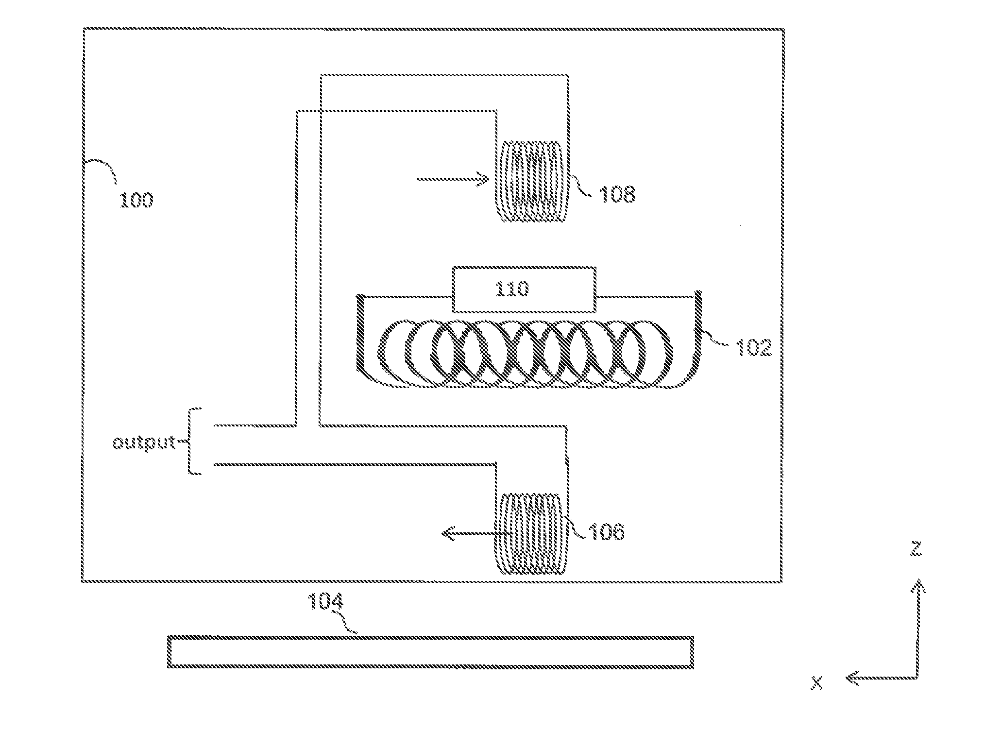
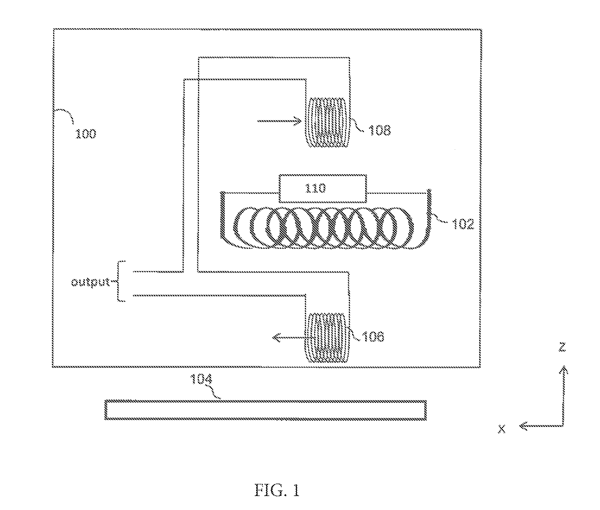
[0044]The sensor coil 106 and the compensatory coil 108 do not have to be wired together. A second embodiment in accordance with an aspect with an aspect of the present invention, will now described with reference to FIG. 2 and in which compensation for the influence of the induction field generated by the inducer coil 102 on the sensor coil 106 is provided by compensatory coil 108 without the two coils being wired together.

[0045]Apparatus 100 can be reconfigured in accordance with a second embodiment such that sense coil 106 and compensation coil 108 are not connected together and instead have respective outputs.

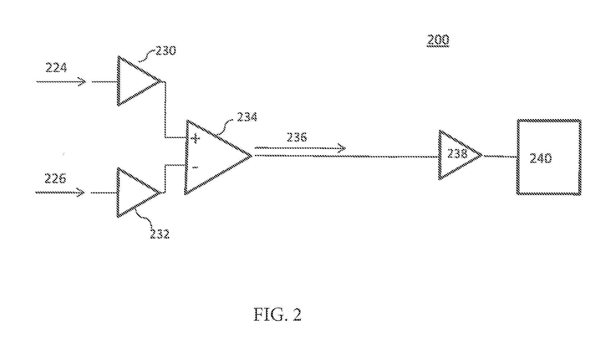
[0046]FIG. 2 illustrates compensation circuitry 200 arranged for receiving from the output 114a sense signal 224 from sensor coil 106 and a compensation signal 226 from compensation coil 108.

[0047]The sense signal 224 and the compensation signal 226 are respectively fed to respective gain elements 230 and 232 where voltage gain is applied to the sense signal 224 and the com...

first embodiment

[0051]It will be evident to persons of ordinary skill in the art that as is usual with differential amplifier configurations, a small residual element of either the sensor signal 224 or compensation signal 226 may be found in the output from the differential amplifier and so the difference or compensated signal 236 is not an exact compensated signal although may be considered to be so within the realms of manufacturing and analytical tolerances. The compensated signal 236 is fed to a gain element 238 which applies voltage gain to the compensated signal 236. The application of voltage gain places the signal into a form that will be useful for electronic instrumentation circuitry 240, inter alia, to display the compensated output of ACFM probe to indicate a defect in the inspection piece. As described previously with respect to the first embodiment, the electronic instrumentation circuitry 240 may provide a real-time output to a display screen or a printer or optionally or additionall...


PUM


Abstract

Apparatus for an alternating current field measurement (ACFM) probe is disclosed. The apparatus comprises an arrangement for generating a magnetic field for inducing an alternating current field in a conductor; a sensor element arranged to produce a signal responsive to the alternating current field; and a compensator element arranged to compensate for an influence of the generated magnetic field in the signal responsive to the alternating current field.

Description

CROSS REFERENCE TO RELATED APPLICATIONS[0001]This application claims the right of priority based on GB application serial no. 1411932.5, filed Jul. 3, 2014, which is incorporated by reference in its entirety.BACKGROUND[0002]1. Field of Art[0003]The present invention relates to an apparatus and a circuit arrangement, in particular, but not exclusively, to an apparatus and circuit arrangement for an alternating current field measurement (ACFM) probe.[0004]2. Description of the Related Art[0005]ACFM is used in the non-destructive testing of conductive materials (a so called “test piece” or “inspection piece”) for defects such as, for example, surface breaking cracks, and other fractures and discontinuities that may occur within the material. The technique has particular application in detecting and sizing surface breaking cracks in ferrite steel structures without requiring access to or contact with the clean (so-called “bright”) metal surface. Therefore, the technique removes the need...

Claims


Application Information

Patent Timeline
IPC IPC(8): G01N27/82
CPCG01N27/82
Inventor PARRAMORE, DAVIDLUGG, MARTIN
Owner TECHN SOFTWARE CONSULTANTS
Why Eureka
Try Eureka